RCMS2304-240 Standalone, Multi Service Fiber Optic, Ethernet Multiplexer User Manual (REV.B) Beijing Raisecom Science & Technology Co.
Raisecom Technology Co., Ltd 1. Cautions Please read the following notices carefully before installing and using the device, Raisecom does not respond to any loss that caused by violating safety notice. RCMS2304-240 provides two types of power supply: AC and DC. When using DC power supply, please plug the power supply connectors according to this mannual strictly and avoid contrary connecting.
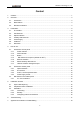
Raisecom Technology Co., Ltd Content 1. Cautions ...........................................................................................................................................1 2. Overview ..........................................................................................................................................4 2.1. 2.2. 2.3. 3. Parameters.......................................................................................................................................
Raisecom Technology Co., Ltd A.1 E1 interface..................................................................................................................................19 A.2 Cable of Ethernet .........................................................................................................................19 A.3 RS232 cable of data channel .......................................................................................................
Raisecom Technology Co., Ltd 2. Overview 2.1. Introduction RCMS2304-240B is an ideal transmission device of optical fiber for point-to-point networks, medium-sized and small capacity networks, such as wireless communication base stations, private communication networks and switch networks. It can be applied to either public networks or various private networks. The transmission capacity of RCMS2304-240 is optional.
Raisecom Technology Co., Ltd RC MS 2 3 04 – 240 / AC AC supply 4 E1 links 4 ports Ethernet Standalone, single strand fiber, 1310nm Switch on layer 2 Multi-service device Company codename (Raisecom) Note: Standalone single strand fiber Ethernet multiplexer: RCMS2304-240 should work with RCMS2504-240, viz. one RCMS2304-240 should connect with one RCMS2504-240.
Raisecom Technology Co., Ltd 3. Parameters 3.1. E1 Interface Bit rate: Line code: Impedance of interface: Electrical characteristics: Transfer characteristics: Input jitter tolerance: 2048Kbps±50ppm HDB3 75Ω (unbalanced BNC interface) or 120Ω (balanced RJ-45 interface) complies with ITU-T G.703 complies with ITU-T G.823 complies with ITU-T G.823 3.2. Fast Ethernet Complied with IEEE 802.3 Ethernet, IEEE 802.3u Fast Ethernet Complied with IEEE 802.3D Spanning Tree, IEEE 802.
Raisecom Technology Co., Ltd Humidity: ≤90% (25℃) 3.7. Dimension Standard 19-inch 1U-high chassis Dimension: 440mm (W)×43.
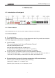
Raisecom Technology Co., Ltd 4. How to use 4.1. Introduction of front panel Sketch of RCMS2304-240 front panel 4.1.1. Power indicator Power indicator (Green): On when the power supply is working in good condition 4.1.2. Alarm indicator z GL: general alarm GL general alarm indicator (red): Any of alarm happened make GL general alarm indicator “on”. Alarm happened on remote site, it is flashing.
Raisecom Technology Co., Ltd 4.1.3. Button z MASK / UNMASK: “ON”: Mask unused E1 link alarm; “OFF”: Not mask unused E1' s alarm z RING / MUTE: Press on: enable the alarm ring. If alarm appears, there will be “zi…zi…” ring. Press off: disable the alarm ring. OFF 4.1.4. DIP-Switch of front panel: (default all “OFF”) ON 123456 12345678 The dip-switches on the front panel are used to set E1 remote loop-back test and Ethernet port isolation functions.
Raisecom Technology Co., Ltd must be all off (no loop-back). z 5th bit: DIP-switch for FPT When FPT is disabled, it is identical to the AIS function of traditional optical multiplexers. When the receiving signals of the E1 interface at the remote site are lost, the corresponding local E1 interface will output all “1” signals; when the receiving signals of the local optical interface are lost, all local E1 interfaces will output all “1” signals. FPT is designed for users who have special requirements.
Raisecom Technology Co., Ltd of remote site. “Isolated on local site” means users of local site isolate each other; but can communicate with remote site. “Isolated oppositely on two sides” means 1st port local site can communicate with 1st port of remote site. So do others. The “TAG” shall be added as per the customer’s requirement.
Raisecom Technology Co., Ltd 4.1.5. Ethernet interface • • • Each RJ45 interface corresponds to one Ethernet port. Refer to Appendix A for wire sequence. Each port is capable of 10/100Mbps auto-sensing MDI/MDIX auto-negotiation 4.1.6. RS232 auxiliary data channel Comply with RS232 standard, use and RJ45 connector. Refer to appendix A for wire sequence. 4.1.7. LINK UP network management port LINK UP port can be connected with the serial port of computer.
Raisecom Technology Co., Ltd 4.2.3. SLOT1, SLOT2 expanded slots Configuration SLOT1 SLOT2 Capability Basic capacity configuration Empty Empty 4 channel E1 SUBM-4E1 (Provides 5th ~8th Empty 8 channel E1 E1) 10BaseT or 10BaseT or V.35sub-system V.35sub-system 4 channel E1 + th (occupied 5 E1) Multi service (occupied 8th E1) multi-service configuration 100BaseT interface Empty (occupied 5th ~8th E1) • Basic capacity configuration: Both Slot 1 and 2 are empty.
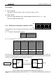
Raisecom Technology Co., Ltd 4.3.1. S1---S4 introduction There are 4 DIP-switches on the bottom. The dip-switch can be set using small sharp pen or tools. Each set of dip-switch is in correspondence with E1 port. Definition as following: 1st 2nd 3rd 4th ON ON ON OFF Or 75Ω unbalanced signal effective As shown in figure above, the default status is interface effective”.
Raisecom Technology Co., Ltd 5. Installation and test 5.1. Inspect after Opening Please first check if the models and part numbers are in consistence, and also check if the equipments are damaged. 5.2. Preparation before Installation z z z z z z Carefully read this manual Prepare all kinds of the cable. Ensure that they are not short-circuited. Refer to Appendix A for cable making. Ensure the pressure of power supply is in the tolerance range, the chassis is well connected with the ground.
Raisecom Technology Co., Ltd 5.3.2. Electrify If power supply (PS) is DC –48V, first connect middle end to PGND. Turn off PS, connect “-48V” end with the lower electric level cable, “0V” end with higher electric level cable. Make sure no reverse connection, or no short circuited, and then turn on power. If PS is AC 220V, use the PS line in the accessories. When PS is turned on, the PWR indicator shall be on. 5.3.3.
Raisecom Technology Co., Ltd 6. Troubleshooting If you have any problems during installation and using, try to solve them by the following proposals. If there is no solution, please contact with distributors for technical support. These following explanations and solutions of alarm for optical port and LOS alarm for E1 tributaries are analyses of local alarm. Please handle it at remote site if there is remote alarm. z Green PWR indicator not on Answer: PS faults.
Raisecom Technology Co., Ltd z LOS red indicator of E1 channel is on Answer: Loss alarm of RX signal at E1 channel, there is no HDB3 signal received. Check if it connects well at E1 port; if the connection of 75 Ω cable reverse and if the string of 75 Ω cable in right order. If there is LOS alarm of unused E1 tributary, can press “mask” button to “on” to make alarm after configuration of device.
Raisecom Technology Co., Ltd 7. Appendix A Introduction of Cable Making A.1 E1 interface z 75ohm adopting DB37 coax adapter: Suggest using SYV 75-2-2 coax cable, the distance less than 200 meter. 120ohm DB37 male connector is defined as following: DB37 pin 1st 2nd 3rd 4th definition OUT 3, 4 7, 8 11, 12 15, 16 IN 21, 22 25, 26 29, 30 33, 34 Others hang up. Twisted pairs can be jointing on DB37 female connector. z A.2 Cable of Ethernet Use RJ45 Cat. 5 twisted-pair cable to connect the equipment.
Raisecom Technology Co.
Raisecom Technology Co., Ltd @2005 Raisecom Technology Co., Ltd. All trademarks are the property of their respective owners. Technical information may be subject to change without prior notification.