User Manual Basic Style KVM Switch 1U KVM Switch with DB-15 Connections Options : »» KVM Over IP »» Remote Console »» 8 or 16 port »» Single or Multi-User
Contents Safety Notice iii 1 Product Overview 1 1-1 Package Content (Standalone KVM) 1-2 Package Content (Integrated KVM) 1-3 Basic Style KVM Table 2 Installation 2-1 2-2 2-3 2-4 2-5 2-6 2-7 Before Installation Unpacking the Unit Installation Instructions (Standalone KVM) KVM Port & CATx Dongle Connection Cascading the KVM Local and Remote Console Diagram Connecting a Remote Console 3 Operation 3-1 3-2 3-3 3-4 3-5 KVM Button Password On-Screen Display (OSD) IP Operations Hotkeys fo
Safety Notice Please read the following before using your Raloy unit: ■■ Unplug equipment before cleaning. Don’t use liquid or spray detergent; use a moist cloth. ■■ Keep equipment away from excessive humidity and heat. Preferably, keep it in an air-conditioned environment with temperatures not exceeding 40º Celsius (104º Fahrenheit). ■■ When installing, place the equipment on a sturdy, level surface to prevent it from accidentally falling and causing damage to other equipment or injury to persons nearby.
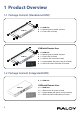
1 Product Overview 1-1 Package Content (Standalone KVM) ■■ 1 x KVM Unit ■■ 1 x Mounting set w/ bracket & screws KVM unit ■■ 1 x Power cord (for KVM) Local USB console KVM with Remote User ■■ 1 x KVM Unit ■■ 1 x Mounting set w/ bracket & screws KVM unit ■■ 1 x Power cord (for KVM) Receiver CAT 5 / 6 cable max.
1-3 Basic Style KVM Table www.Raloy.com/support/downloads.
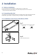
2 Installation 2-1 Before Installation ■■ It is very important to mount the equipment in a suitable cabinet or on a stable surface. ■■ Make sure the place has a good ventilation, is out of direct sunlight, away from sources of excessive dust, dirt, heat, water, moisture and vibration. 2-2 Unpacking the Unit The equipment comes with the standard parts shown in package content. Check and make sure they are included and in good condition. If anything is missing, or damaged, contact Raloy immediately.
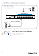
2-4 KVM Port & CATx Dongle Connection CE-6 / CE-10 / CE-15 ■ 6 / 10 / 15 ft Combo KVM cable ■ Support PS/2 or USB server USB Servers RDB-15 Combo KVM port PS/2 Servers RCE - 6 / 10 / 15 Combo KVM cable support PS/2 or USB server RCE-6 / RCE-10 / RCE-15 Combo KVM Cable ■■ 6 / 10 / 15 ft.
2-5 Cascading the KVM Raloy KVMs CATx10008 / CATx10016 / CATx10032 can be cascaded. ■■ Cascade up to 8 levels (256 servers max) ■■ Cascade multiple KVM Switches with RCBC-6 cascade cable.
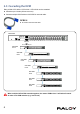
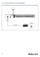
2-6 Local and Remote Console Diagram 6
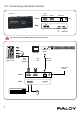
2-7 Connecting a Remote Console Receiver Local Computer Monitor Remote I/O Front Rear Power USB K/B Mouse Local Button to PC Remote Button to KVM switch The receiver provides a hotkey function for remote console.
3 Operation 3-1 KVM Button Power ON ■■ Turn off all servers and KVM switches ■■ Make sure all cables / connectors are properly connected ■■ Power ON sequence 1. Turn on Rack Monitor (if applicable) 2. Turn on KVM switch 3. Turn on Servers Front Panel - Port LED Indications 8 ports Bank no. PC port LEDs Channel button Bank button 16 ports 32 ports Bank no.
3-2 Password The password is enabled by default. The default password is “00000000” (Do not use “0” on number pad) ■■ Enable password 1. Press the KVM hotkey Scroll Lock + Scroll Lock + U 2. Logout of the KVM by pressing the hotkey Scroll Lock + Scroll Lock + P 3. In SUPERVISOR level, enter “00000000” in both the user name & password fields (Do not use “0” on number pad) 4. In USER level, press Space bar + Enter in user name & password field 5.
3-3 On-Screen Display (OSD) OSD Menu OSD operation next to the system name The PC is powered on next to the system name The PC is selected F1 Access F1 MAIN MENU F2 Logout of the OSD menu F3 Previous menu Esc Cancel / Quit Enter Complete / Switch to selected port Switch to previous or next port PgUp/PgDn Switch to previous bank or next bank 1/2/3/4 Display port 01 ~ 08 / 09 ~ 16 / 17 ~ 24 / 25 ~ 32 Remark: Display port 17 ~ 32 for 32 port model only F1 Main Menu 10 01 LANGUAGE OSD lang
3-4 IP Operations Please refer to the IP Manual for information on how to set-up and use the IP functions on compatible Raloy KVM Switches. The IP Manual can be found at www.Raloy.com/files/Raloy-KVM-IP-Manual.
4 Product Specifications 4-1 Specifications Table Product Information Dimensions (W x D x H) Gross Weight Packaging Information Dimensions (W x D x H) Gross Weight Environmental -5 to 60 °C (23 to 140 °F) Number of Ports Connector Connectivity Graphic Connector Resolution Input Device Connector DB-15 Combo Combo 4-in-1 KVM Cable Up to 6, 10, and 15 feet 1 x DB-15 VGA Up to 1600 x 1200 2 x USB type A (keyboard & mouse) 2 x USB type A (keyboard & mouse) RJ45 via CAT6/CAT5e/CAT5 cable up to 500 feet A
4-2 DC Power: 12V, 24V, 48V Input Model 12V 24V 48V Input rating Input voltage: 12-Volt 24-Volt 48-Volt Input range: 9 ~ 18V 18 ~ 36V 36 ~ 75V - No load 50 mA 50 mA 50 mA - Full load 4950 mA 2450 mA 1220 mA Output voltage: 12-Volt 12-Volt 12-Volt Output current: 4.16A 4.16A 4.
5 Important Information Warranty Information I. Raloy Limited Warranty Raloy Customer Support warrants to the original retail purchaser that this product is and will be free from defects in materials and workmanship for a period of twenty-four (24) months from date of purchase. During the warranty period, the purchaser must promptly contact Raloy Tech Support for assistance to report a unit failure. II. Warranty Period 1.
What the Warranty Does Not Cover ■■ Any product, on which the serial number has been defaced, modified or removed. ■■ Damage, deterioration or malfunction resulting from: ■■ Accident, misuse, neglect, fire, water, lightning, or other acts of nature, unauthorized product modification, or failure to follow instructions supplied with the product. ■■ Repair or attempted repair by anyone not authorized by us. ■■ Any damage of the product due to shipment. ■■ Removal or installation of the product.