Versatile H.264 DVR User’s Manual Version 1.
DVR User’s Manual 1
DVR User’s Manual Caution and Preventive Tips • Handle with care, do not drop the unit. • Mount the unit in an equipment rack or place it on a solid, stable surface. • Indoor use only. Do not place the unit in a humid, dusty, oily, or smoky site. • Do not place it in an area with poor ventilation or in an area close to fire or other sources of heat. Doing so may damage the unit as well as cause fire or an electric shock.
DVR User’s Manual Important Information Before proceeding, please read and observe all instructions and warnings in this manual. Retain this manual with the original bill of sale for future reference and, if necessary, warranty service. When unpacking your unit, check for missing or damaged items. If any item is missing, or if damage is evident, DO NOT INSTALL OR OPERATE THIS PRODUCT. Contact your dealer for assistance.
DVR User’s Manual Table of Content 1. Overview .......................................................................................................................7 2. System Setup................................................................................................................8 2.1 Position the Unit...................................................................................................8 2.2 Selecting Video Format..................................................................
DVR User’s Manual 4.1.4 4.2 4.3 4.4 4.5 Viewing Recorded Video ......................................................................28 Key Usage in Playback ........................................................................29 Pause Playback and Single Step Forward ...........................................29 Sequence Setup ................................................................................................30 4.2.1 Sequence with Main Monitor .........................................
DVR User’s Manual 5.3.6 5.3.7 Take a Snapshot...................................................................................50 Remote Monitoring Software Trouble Shooting Guide .........................51 Appendix A: Technical Specifications ...........................................................................52 Appendix B: Connect UTP Camera ................................................................................54 Appendix C: Connect Analog Camera via UTP Converter ...................
DVR User’s Manual 1. Overview The Versatile H.264 DVR is an integrated digital video recorder that combines the features of a time-lapse audio / video recorder, a multiplexer, and a video server to create a single security solution. Its outstanding triplex operation enables users to view live video, search and playback any recorded video by date/time or event, and remotely monitor the unit via internet on PC, MEANWHILE the recording of the DVR unit is ongoing simultaneously. The Versatile H.
DVR User’s Manual 2. System Setup The notices and introduction on system installation will be described particularly in this chapter. Please follow the description to operate the unit. In order to prevent the unit from data loss and system damage that caused by a sudden power fluctuation, use of an Uninterruptible Power Supply (UPS) is highly recommended 2.1 Position the Unit First, note to position / mount the DVR in a proper place and be sure to power off the unit before making any connections.
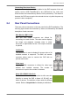
DVR User’s Manual Connecting Short-term Device If any short-term devices shall be installed to the DVR as parts of the unit system, such as USB ThumbDrive® or any USB devices, etc, make sure those devices are connected only after the unit is powered up. The reason is because the DVR can recognize the external devices only after the power-up process is done completely. 2.4 Rear Panel Connections There are various connectors on the rear panel for the DVR installations.
DVR User’s Manual LAN Connector (RJ-45) The DVR is capable of networking. Once the unit is connected to the LAN network, users can remotely access the unit through the remote software on a PC. USB Connector (x3) There are three USB 2.0 ports (2 at rear + 1 at front) to allow users to connect external USB devices to the unit, such as a USB ThumbDrive® or a USB mouse. Power Jack The DVR has a free voltage DC power connection jack. Please connect the power adapter shipped with the unit.
DVR User’s Manual 3. General System Setup Before operating the DVR, some general configuration should be setup first. The following subsections will introduce function keys on the front panel and general configuration of the DVR. The regular displayed OSD information and its displayed positions are shown as following figure. Title of the channel will be displayed on the top-left corner of the window, either in full screen mode or in multiple channel mode.
DVR User’s Manual 3.1.2 Function Keys This section describes the functional keys, which are for normal operation, on the front panel of the DVR. Please refer to the Setup Guide for the graphical illustration of functional keys. CHANNEL • In both Live and Playback modes, press the CHANNEL key to view the corresponding video in full screen. The number of the CHANNEL keys corresponds to the number of cameras supported by the unit.
DVR User’s Manual COPY In Playback mode, press COPY to select the start and end time of the export video. Refer to Section Video Export for detailed information. CALL • In Live mode, press this button to enter call monitor control mode. • In Dome Control mode, press CALL in association with ENTER to enter the OSD setup menu of the dome camera. • In OSD virtual keyboard, press this key to input a period mark “.”. DOME • Press the key to enter dome control mode.
DVR User’s Manual SEARCH In both Playback and Live mode, press SEARCH to enter the Search menu for searching and playing back recorded video by date and time or events. 3.2 Entering OSD Setup Menu The configuration of the DVR can be customized by entering the intuitive Graphical User Interface (GUI) OSD setup menu. Collaborating with a USB mouse, setting up the DVR can be easy as operating on a PC. Press MENU and input a valid username. There are two preset accounts: “admin” and “user”.
DVR User’s Manual Before completely logout, other functions can also be accessed without having to login again. There are two ways to logout: manually logout by pressing ESC key at Live mode, or auto logout when keys are not pressed for 5 minutes at Live/ Menu mode. 3.2.1 User Management The DVR provides the option to create up to seven sets of usernames and passwords with customized authority, excluding the preset “admin” account.
DVR User’s Manual When the account does not have authority to access certain functions, an error message will be displayed on the screen. Load Default Setting Select to load the default setting. 3.3 Power Up / Down the Unit If the DVR must be shutdown for any reason, please use the proper shut down and power up procedures to avoid damaging the DVR. To Power Up the Unit Simply plug in the power adapter that came with the package and the DVR will start to boot.
DVR User’s Manual 3.4 System Date / Time Setting Users can set the current date, time and other OSD parameters in Date/Time menu (under System Setup menu). The login account should have authority to access the System Setup menu. In OSD setup menu, select and press ENTER, then select to access the Date/Time menu; the menu displays as follows. Date/Time Date Time Date/Time Display Date Display Mode Time Display Mode Date/Time Order Daylight Saving Time Setup 3.4.
DVR User’s Manual Date Display Mode This function allows users to set the OSD display type of the date. There are three options to select from: , or . “Y” represents “Year”, “M” represents “Month” and “D” represents “Day”. Move to the item and press ENTER, the option starts blinking. Use UP / DOWN keys to change the setting. Time Display Mode Users can set the time format to <12 hour> or <24 hour>. Use the UP / DOWN keys to change the format.
DVR User’s Manual 3.5 IP Camera Setting The distinctive hybrid solution of the DVR enables users to connect IP camera(s) while others are analog cameras. First enter the OSD setup menu with a proper account and access Æ to select the number of IP cameras to be connected. The supported channels of IP cameras will be from the largest numbers, for example CH16 for 16ch models. NOTE: The DVR must be rebooted in order to apply the change of IP Camera Support option.
DVR User’s Manual 3.5.2 Connection Setup Enter to configure the connection and data transmission setting of the connected IP Camera. The menu will be shown as below. Connection Setup Account Password Management Port Streaming Format Advance Streaming Option Streaming Port Streaming Protocol IP Dome Protocol **** **** 80 MPEG4 OFF 554 RTP+RTSP None Account / Password Access these two items to enter a valid account name and password of the connected IP camera.
DVR User’s Manual IP Dome Protocol If the connected device is an IP Dome Camera, then select an appropriate IP Dome Protocol from the provided options. 3.5.3 Device Setup Enter to configure the basic settings of the IP camera. The basic settings include the IP camera’s product name, image quality, image adjustment, etc. Set the item to to apply the changes. NOTE: The administrator account and password of the IP camera should be entered in order to change the basic settings.
DVR User’s Manual 3.6 Record Schedule / Quality Setting The Record Setup menu allows users to set recording quality, recording schedules, and other recording parameters. Login with a proper account to access Record Setup menu. In the Main menu, move the cursor to and press ENTER; the following menu is displayed. Record Setup Record Mode Setup Schedule Setup Preset Config Per Camera Config ezRecord Setup Data Lifetime Circular Recording Audio Recording Purge Data 3.6.
DVR User’s Manual 3.6.2 Preset Record Configuration The is used to select the preset recording quality and frame rate. In normal circumstances, it is strongly recommended to set the preset configuration as . Below table shows the PPS and picture size under in Half-D1 mode. Please refer to OSD Setup Manual, Section Preset Record Configuration for more detailed information.
DVR User’s Manual 3.6.4 Record Event Video Only If the DVR shall start recording only when alarms are triggered, follow the steps below: • Enter the OSD setup menu with a proper account. • In the OSD setup menu, select menu. Move the cursor to the item , and select . Refer to OSD Setup Manual, Section Preset Record Configuration for further information. 3.6.
DVR User’s Manual • Select and press ENTER, then press UP/DOWN to make a choice. The will be computed automatically. • Select and press ENTER, then press UP/DOWN to make a choice. The will be computed automatically. NOTE: The current number of connected cameras will affect the recording quality automatically calculated through the .
DVR User’s Manual 3.6.8 Audio Recording When an audio source device is connected, it will be automatically set to , audio input is recorded and saved with the video. When no audio source device is connected, it will be automatically set to . 3.6.9 Purge Data This item is used to delete the Normal or Event recording video. In Record Setup menu, move the cursor to and press ENTER; the Purge Data menu is displayed.
DVR User’s Manual 4. Basic Operation The DVR allows users to access some general operations through the front panel easily. The following sections introduce the general operations of the unit. 4.1 Viewing Live / Playback Video The general functions in live and playback mode are described in the following sections. 4.1.1 Viewing Modes The DVR provides users versatile ways of viewing both live and recorded video. Following presents these view formats.
DVR User’s Manual 4.1.2 Digital Zoom Users are able to view a 2× full screen in live mode. To view the 2× full screen, follow the steps. • Press any CHANNEL key to view the corresponding camera in full screen. • Press ENTER to view 2× zoomed screen of the selected camera. • To view a specific area in 2× zoomed screen, use Direction keys to pan / tilt the zoomed screen. • Either press ENTER again or ESC to leave the Zoom mode. 4.1.
DVR User’s Manual The general operations in playback mode are described as follows. Key Usage in Playback The key usage is slightly different in playback mode. Following is the key usage found in playback mode. z LEFT (Reverse Playback) The key is used to reverse the recorded video while the unit is playing back. Press the key repeatedly to increase the speed of reverse playback by 1×, 2×, 4×, 8×, 16×, or 32×. z RIGHT (Forward Playback) The key is used to play the recorded video fast forward.
DVR User’s Manual 4.2 Sequence Setup This section introduces the way to view sequence mode with both Main Monitor and Call Monitor, if connected. Sequence function can avoid manual backtracking and provides more flexibility while monitoring surveillance. 4.2.1 Sequence with Main Monitor Automatic sequence function can be observed in any view mode. Select certain view format and press SEQ to toggle the automatic sequence; press ESC to stop sequencing.
DVR User’s Manual 4.3 Searching Recorded Video The DVR is capable of searching and playing back recorded video by date and time or events. Enter the specific date and time of the wanted video, the DVR will search for matched video and start to playback the video. Alternatively, users can search for event video by channel as well. In live or playback mode, press SEARCH to enter the Search menu, which is shown as follows.
DVR User’s Manual 4.3.2 Searching by Event “Event List” allows users to search wanted video by event. The Event List is displayed as below figure: Event List First Page Date 2008/03/17 2008/03/17 2008/03/16 2008/03/15 2008/03/12 2008/03/12 2008/03/11 2008/03/10 2008/03/08 2008/03/08 2008/03/08 Time 11:26:50 09:53:03 16:14:42 03:45:31 22:27:56 10:09:29 12:18:20 05:16:00 17:11:37 16:29:10 03:22:17 Ch.
DVR User’s Manual 4.4 Video Export The unit allows users to export wanted video to the built-in DVD+RW or an external device, such as a USB ThumbDrive, and the exported video will be saved as *.drv file. If the video is to be exported to an external device, make sure the device is connected to the DVR unit and the port has been set appropriately for video export. NOTE: Once an external device is connected to the DVR unit, the device has priority over the built-in DVD+RW.
DVR User’s Manual 4.4.2 Export Normal Video To Export normal video to external device, follow these step: • Press SEARCH and play wanted normal video by entering date and time. Note if the screen is showing in multiple channel mode, please make sure there is no window displaying in Live mode, or the export will not work. • After entering playback mode, play the video and press COPY once to mark the starting point of the export video. The playback continues.
DVR User’s Manual 4.4.3 Export Event Video To export event video, follow these steps: • Press SEARCH and play wanted event video. To play event video, refer to Section Searching Recorded Video. • After entering the playback mode, press COPY. The “ezBurn” window will display as below figure. The information shown is “read only”. ezBurn confirmation Selected Device: Built-in-DVD+RW All data on the disc will be erased.
DVR User’s Manual 4.5.2 Dome Protocol Setup The Dome Protocol item lists the available dome protocols for communicating with dome cameras connected to the DVR. From the Main menu, select and press ENTER. The following menu is displayed.
DVR User’s Manual The ID number must match the ID address set by the dome. The Unit ID is in the range of 1 to 255. Note that there cannot be any two devices on the same bus given the same ID address, or a conflict may occur. NOTE: The settings become effective after saving the changes and exiting from the menu. 4.5.4 Dome Controlling Keys The functions of some keys in dome control mode are totally different from normal status function.
DVR User’s Manual Auto / Enter • In OSD setup menu interface, the key is used to make selection. • In dome control mode, this key is used to activate automatic focus and iris function. Iris Close Use to close the Iris on the dome camera. Focus Far Use to focus the selected dome camera far. Zoom Out Use to zoom out the dome camera. This function enables users to shrink the current image and view a larger area. Pan / Tilt Use to pan and tilt dome camera. 4.5.
DVR User’s Manual • Press 1 to access the Set/Go Preset function. The Dome Preset menu is displayed. Dome Preset First Page Index 1 2 3 4 5 6 7 Set Preset No No No No No No No Go Preset No No No No No No No • Use UP / DOWN keys to select the desired preset number from the menu. • Set the of the selected preset number to , and press ENTER to save the position. Now the preset is set and ready to be called. 4.5.6 Calling Preset Points Follow the steps to call preset points.
DVR User’s Manual 5. Remote Monitoring Software The remote monitoring software is a remote browser-based software application designed to operate with the DVR products. Using the software, users are allowed to view live and recorded video, and configure the DVRs remotely via a LAN, WAN or Internet on a personal computer. The connected PC will automatically download the remote monitoring software plug-ins from the DVR when the DVR is connected by entering its IP address in the address bar on the browser.
DVR User’s Manual 5.2 Getting Start of Installation Refer to the following description to install the remote monitoring software. 5.2.1 Changing Internet Settings The PC operating with the remote monitoring software should be set to accept ActiveX plug-ins. Please follow the steps to set the Internet security settings appropriately. • Before operating the remote monitoring software, please check the IP address of the DVR.
DVR User’s Manual • Uncheck “Require server verification (https:) for all sites in this zone”. Type the IP address of the unit in field and click to add this web site to the zone. • Click to confirm the setting and close Trusted sites dialog. • In the Security Level area, click . The Security Settings screen is displayed. • Under , set all items to or . • Click to apply the setting and close the screen.
DVR User’s Manual 5.2.2 Install Remote Monitoring Software Start the browser to initiate the installation of the remote monitoring software on the PC. The IP address of the DVR can be saved as a Favorites item in the web browser to enable easy access in the future. • Start the IE; it can be started either by clicking on the desktop icon, or by using the Start menu to access it. • Enter the IP address of the DVR in the address bar at the top of the browser.
DVR User’s Manual 5.2.2.1 Login / Logout Login using the same accounts setup in the DVR. The authority is also the same as setup in the DVR. One preset account “admin” and up to two other accounts can access a DVR at the same time. Nevertheless, if the “admin” account is currently accessing the unit’s OSD setup menu via front panel of the unit, then the “admin” account at the remote monitoring site cannot change the settings at the same time. The “admin” account of the DVR has priority.
DVR User’s Manual 5.2.2.2 Software Upgrades If a new version of the remote monitoring software is available on the DVR, upgrade will be prompted while accessing the unit. Follow the steps to upgrade the software. • The message as the above figure will be prompted. Click to accept version upgrade. • Start the IE again and enter the IP address of the DVR in the Address bar of the browser; or if the unit address is set as a Favorite site, click the Favorites entry for the unit.
DVR User’s Manual 5.3.1.1 Select Display Mode Choose the number of windows to be displayed on the main window. Click one of the display buttons in MODE section. Available selections are 4, 9 and 16 camera displays. To view certain window in full screen, either double-click on the wanted window, or click on the corresponding CAMERA button. 5.3.1.2 Operate Cameras with Dome Control The remote monitoring software allows users to control and configure a dome camera remotely.
DVR User’s Manual Focus +/− Use to adjust the camera lens to focus on objects for a clear view. Click on to focus near or to focus far. Iris +/− This item is used to open and close the iris to let more or less light into the camera. Click on to open iris or to close iris. Zoom +/− Users are allowed to zoom-in or zoom-out using the adjusting buttons. Zoom-in to enlarge a certain area and zoom-out to view more area.
DVR User’s Manual 5.3.3 Playback Video The remote monitoring software allows users to either view recorded video from the DVR, or from the hard disk drive of the PC. To access the Playback screen, click button on the main window toolbar. There are three tabs in the Playback screen: , , and tabs. allows users to play back from the DVR. enables users to playback a recorded video file stored on the hard disk drive of the PC.
DVR User’s Manual • The other option in
DVR User’s Manual 5.3.4 Verify Digital Signature The digital signature aims to authenticate a video file exported from the unit. Follow the description to verify the digital signature. • Click on the main window toolbar. • Click tab to display the Verify window. • Click to select the *.gpg, *.avi, *.sig files respectively, which belong to the exported video to be authenticated. • Click to start verifying digital signature.
DVR User’s Manual 5.3.7 Remote Monitoring Software Trouble Shooting Guide What happened if the server requests to upgrade the software every time the DVR is connected? If the following screen displays repeatedly, please follow the steps to delete the temporary internet files. • Select from the main menu of the web browser, then , and then click the tab.
DVR User’s Manual Appendix A: Technical Specifications All specifications are subject to change without notice. Specifications Video Operation System Input 4ch Model 8ch Model 16ch Model Embedded ( Linux ) BNC×16, 1.0Vp-p, 75 ohm 4ch UTP 8ch UTP 16ch UTP Up to 2ch Up to 4ch BNC × 1, 1.0Vp-p, 75 ohm BNC × 1, 1.0Vp-p, 75 ohm 800 × 600, 1024 × 768, 1280 × 1024 pixels@60 Hz (Optional) NTSC: 30 PPS/Per channel, PAL: 25 PPS/Per channel BNC×4, 1.0Vp-p, 75 ohm BNC×8, 1.
DVR User’s Manual General Unit Dimension (W×H×D) Unit Weight Package Dimension (W×H×D) Package Weight Operation Temperature Relative Humidity Power Consumption & Input 362 × 90 × 350 mm (14.2 × 3.5 × 13.7 inches) 5.5 Kg (12.1 lbs) 410 × 210 × 500 mm (16.1 × 8.2 × 19.6 inches) 7 Kg (15.
DVR User’s Manual Appendix B: Connect UTP Camera UTP, short for Unshielded Twisted Pair, is a popular type of cables that is one of the most common medium in telecommunication industry. Installing the UTP module allows the DVR to supply power to and transmit images from any four distinctive UTP cameras through the UTP cables (CAT5). This leads to an economical and fast installation of surveillance.
DVR User’s Manual Follow the same procedure if more UTP Cameras to CH2, CH3, or CH4 will be installed. NOTE: Do NOT insert both BNC and UTP video sources to the same channel simultaneously, or the video will not function correctly and it may cause the video to look like the figure below. For instance, if a UTP Camera is already installed to channel 1, do not install another camera to the BNC port of channel 1. Bad Video Output Step 3: Plug in the power adapter to the DVR, and the DVR will start to boot.
DVR User’s Manual Appendix C: Connect Analog Camera via UTP Converter Introduction: The UTP converter is made especially for users who want to build a connection between an UTP DVR and a traditional analog camera, which allows the transmission of power and video signal through one CAT5 cable. The UTP converter has two cables at one end: one cable for connecting with the camera’s BNC video connector; the other for connecting with power jack of the camera.
DVR User’s Manual Appendix D: Recommended HDDs Refer to the following list for some recommended HDDs to be used in the DVR. Brand Model Name Model Number Size Barracuda ES.2 ST3500320NS 500G Barracuda 7200.11 ST3500320AS 500G Barracuda 7200.11 ST3750330AS 750G Barracuda 7200.
DVR User’s Manual Appendix E: IP Camera Installation The following is an example of the installation of a NH Series IP camera. Step 1. Enter the IP address (for example: 192.168.1.242) of the NH Series IP camera to access its web management page. Login using the administrator’s username and password (for example: Admin & 1234). Step 2. Access the System menu and click on the “Network” tab to find the management port and the RTSP port. The management port is 80 and the RTSP port is 554.
DVR User’s Manual Step 3. Next click on the “View parameters” tab to look for current camera image settings: Brightness=25, Sharpness=128, and Contrast=128. Step 4. Access the Streaming menu to look resolution setting: MJPEG=1280x960, MPEG-4=VGA, and the maximum frame rate is 15fps.
DVR User’s Manual Step 5. Access the OSD setup menu of the DVR to select the number of IP cameras to be connected: Æ . The DVR will reboot in order to apply the change. Step 6. Access the menu of the DVR to setup the IP camera. Select the channel that is reserved for IP camera. The menu should look like the following: IP Camera CH16 CH16 192.168.1.
DVR User’s Manual Step 10. Set to and the device setting parameters will be applied. Step 11. Set Æ to and the video from the IP camera should be displaying on the screen after a few seconds. Step 12. Access Æ and the current status of the IP camera will be displayed as shown below. The information is “read only”. Status Model Streaming Format Resolution PPS Bandwidth Pkg. lost rate NH Series MPEG4 640x480 15.00 62.53 KB/Sec 0.
DVR User’s Manual Appendix F: Remote Controller The operational function keys (on the left) and dome camera control keys (on the right) on the remote control are listed as below figure: 62
DVR User’s Manual The keys of the remote control function as the keys of the front panel of the DVR. The only difference between the remote control and the front panel keys is the “DVR SEL” key. The DVR Selection key is used to switch control between each DVR. The remote control can be used to control up to 16 DVRs. To setup the remote control, the first thing is to assign a unique DVR Unit ID to each DVR.
DVR User’s Manual Appendix G: Setting up a DVR behind a Router This appendix describes how to set up a router if the DVR connects to the internet via a router. To properly operate a web server, e.g. a DVR, users have to set up both the IP and port of the DVR, which are essential for data and command transmission. The port setting is adjustable in OSD setup menu of the DVR and only one port is needed to do remote operation.
DVR User’s Manual Following is an example of how the router should be set. Router (D-Link DI-724P+) WAN IP: 218.160.54.13 LAN IP: 192.168.0.1 PC IP: 192.168.0.100 DVR 1 IP: 192.168.0.167 Trigger port: 80 DVR 2 IP: 192.168.0.200 Trigger port: 81 • To change the setting of the router, a PC with web browser is required. • Connect to D-Link DI-724P+ from PC via IE. The setup screen will be shown after entering the correct username and password.
DVR User’s Manual A. Select to set up the service. B. Enter the name of the setting in the Name field: DVR 1. C. Enter Private IP: 167 D. Choose as the Protocol Type. E. Enter Private Port: 80. F. Enter Public Port: 80. G. Click for the Schedule setting. H. Click . • Click to go on when the following screen displays. • Follow the steps to set up web port forward to DVR 2. A. Click to set up the service. B.