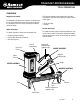
TRAKFAST REPAIR MANUAL Tool Repair Manual
TRAKFAST REPAIR MANUAL TABLE OF CONTENTS Safety Instructions. . . . . . . . . . . . . . . . . . . . . . . . . . . . . . . . . . . . . . . . . . . . . . . . . . . . . . . . . . . . . . . . . . . . . . . . . 3 Tool Operation Overview. . . . . . . . . . . . . . . . . . . . . . . . . . . . . . . . . . . . . . . . . . . . . . . . . . . . . . . . . . . . . . . . . . . . . . . . . . . . . 6 Start and Pre-Combustion . . . . . . . . . . . . . . . . . . . . . . . . . . . . . . . . . . . . . . . .
TRAKFAST REPAIR MANUAL • • • • • • • • • • • • • 5/32” Hex Key Inside Snap Ring Pliers Outside Snap Ring Pliers #2 Phillips Screwdriver T15 Torx Screwdriver T25 Torx Screwdriver T7 Torx Screwdriver Flat Blade Screwdriver Needle Nose Pliers Lubricating Oil Loctite #343 Blue RTV Silicone Volt/Ohm Meter (is helpful) Rev.
TRAKFAST REPAIR MANUAL SAFETY INSTRUCTIONS The following safety instructions have been included to provide you with information necessary for safe operation of the TrakFast Tool. WARNING HIERARCHY WARNING DANGER Failure to follow all instructions may result in severe personal injury or substantial damage to tool and/or personal property. WARNING When servicing tool, stay clear of high voltage ignition cable. High voltage may be present in unexpected areas with malfunctioning tools.
TRAKFAST REPAIR MANUAL SAFETY INSTRUCTIONS 1. Wear eye and ear protection. The fastener may be accidently discharged. 9. DANGER Always wear EYE and EAR safety gear when working with or in the vicinity of the TrakFast tool. 2. ALWAYS assume the tool is “loaded”. 3. DON’T treat the TrakFast tool as a toy. The TrakFast tool is not a toy — it is a tool. Careless and improper use may result in a serious accident. 4. NEVER carry the tool with your finger on or pressing the trigger.
TRAKFAST REPAIR MANUAL SAFETY INSTRUCTIONS 15. Fuel Cell Storage 6. DANGER Insert the battery, contact side down, into the charger and depress red button. The green light will go out and the red light will come on, indicating the battery is charging. 7. Always store fuel cells where they will not be exposed to an open flame, sparks or temperatures above 120 degrees F (48 degrees C). 16. ALWAYS store the tool with the fuel cell removed. 17. Keep the tool clean. 18.
TRAKFAST REPAIR MANUAL TOOL OPERATION OVERVIEW Magazine Assembly The magazine assembly has two functions. Its primary function is to store and feed fasteners into the nose of the tool. Its secondary function is to house the battery and battery contact assembly. This assembly generates and controls forces that drive the fasteners. It will require the majority of routine service and/or repair.
TRAKFAST REPAIR MANUAL TOOL OPERATION START and PRE-COMBUSTION When lower probe (E) is pressed against the work surface, cage (F) is forced against the spring (G). Combustion chamber (H) is raised up against cylinder head (I), and O-Rings (J & M) seal off the combustion chamber, creating an air tight seal. This initial movement, pressing the lower probe against the work surface, causes the fuel cell/metering valve assembly to pivot.
TRAKFAST REPAIR MANUAL TOOL OPERATION Combustion Depressing the trigger activates the ignition circuit. This causes a spark (N) to jump the gap between the spark element and cylinder head, igniting the fuel/air mixture in the combustion chamber. Piston assembly (O) is forced downward driving the fastener into the work surface. Rev.
TRAKFAST REPAIR MANUAL TOOL OPERATION Power/Exhaust Downward movement of the piston assembly, past exhaust ports (P), allows exhaust gases to exit. The pressure of the exhaust gases against the flat washer compresses the wave washers, allowing the gases to flow through the mid-check area (Q) and out of the tool through the exhaust ports in the bottom of the housing (R). At the bottom of stroke, the piston assembly strikes bumper (S). Rev.
TRAKFAST REPAIR MANUAL TOOL OPERATION Return Reduced pressure within the combustion chamber allows wave washers (T) to reseal the combustion chamber. Rapid cooling of gases trapped in the combustion chamber (U) creates vacuum. This vacuum is strong enough to lift and hold the piston assembly in its starting position. As the piston assembly moves up the sleeve, air is drawn in through ports in the housing nose (V). Rev.
TRAKFAST REPAIR MANUAL TOOL OPERATION Purging The combustion chamber drops when the tool is lifted from the work surface and the trigger is released. This opens the seal between the combustion chamber and cylinder head O-Ring (W) and sleeve O-Ring (X). The fan is now able to circulate fresh air into the combustion chamber, cooling the sleeve (Y) and purging any remaining exhaust gases from the tool through ports (Z). Rev.
TRAKFAST REPAIR MANUAL TROUBLESHOOTING Preparing Tool for Operation — Battery/Charger Problems SYMPTOM Battery Cell doesn’t appear to accept charge — green Charger light does not come on — red Charger light comes on when Battery Cell is inserted in Charger. Battery is inserted into Charger and no red LED. POSSIBLE PROBLEMS SERVICE Inoperative indicator lights on Charger. Try Battery Cell in tool after charge cycle. If tool LED is green, Charger lights are not working properly.
TRAKFAST REPAIR MANUAL TOOL DISASSEMBLY DANGER ALWAYS TAKE THE FOLLOWING PRECAUTIONS BEFORE ANY SERVICE OR ROUTING MAINTENANCE IS PERFORMED: • REMOVE FASTENERS • REMOVE FUEL CELL • REMOVE BATTERY REMOVE THE MAGAZINE ASSEMBLY Loosen and remove knob (part #801124). Slide the magazine back and away from nose. Rev.
TRAKFAST REPAIR MANUAL TOOL DISASSEMBLY REMOVE HANDLE ASSEMBLY (Part 1) Lift off cap, grill and filter with screw driver. Loosen four screws using a 5/32” hex key (Part # 7405061). Lift off cap assembly (Part # 401365). Rev.
TRAKFAST REPAIR MANUAL REMOVE HANDLE ASSEMBLY (Part 1) Remove Screw at bottom of Handle Assembly (Part # 7405065). Remove Cam Bushing.(Part # 401397). Push Cam Bushing out of Handle from side where the Screw was removed. Rev.
TRAKFAST REPAIR MANUAL TOOL DISASSEMBLY REMOVE MOTOR ASSEMBLY Pull Handle Assembly away from Motor Assembly until fan clears combustion chamber assembly. Do not scratch combustion chamber walls with fan blades. Set Handle Assembly down carefully so that Fan Blades are not damaged and Fan Motor Shaft is not bent. When removing handle from housing, be sure not to bend fan blades. CAUTION Be sure leads and connectors are positioned so that leads are not pinched when installing cap.
TRAKFAST REPAIR MANUAL TOOL DISASSEMBLY Motor/Cylinder Head Assembly Torque Head Switch to 5-10 in-lbs. Torque Spark Plug to 20-25 in-lbs. Install Stem Adapter as illustrated. Notice the difference between one end of the Sleeve to the other. One side of the sleeve has a rib. The other side does not. The ribs should be to the inside and should touch the fan motor. **CRITICAL** Install the Motor Sleeve as illustrated.
TRAKFAST REPAIR MANUAL Motor/Cylinder Head Assembly (cont’d) Apply a small amount of oil or lubricant to the inside of the bore where the Fan Motor is positioned. Insert Motor Assembly as illustrated. The Motor Sleeve orientation will determine how well the spacing will be around the shaft. Make sure that it is equally spaced all the way around. SOMETIMES you may have to adjust the Motor Sleeve clockwise or counterclockwise to help center the shaft. Rev.
TRAKFAST REPAIR MANUAL TOOL DISASSEMBLY Motor/Cylinder Head Assembly (cont’d) Make sure the “flat” side of the shaft is where the Set Screw on the Fan Blade will be tightened. Position the Fan Blade approximately .120” away from the bottom of the cylinder head. Feeler Gages or an 1/8” drill bit works well as a spacer. Carefully place the Fan Blade until it is flat and leveled over the Fan Blade Spacer. Tighten Set Screw no more than 8 to 10 in-lbs of torque. Rev.
TRAKFAST REPAIR MANUAL TOOL DISASSEMBLY CYLINDER HEAD ASSEMBLY KEY PART NO. DESCRIPTION 1 401365 Cap, grill & filter assembly 3 7505018 Foam filter only 4 901065A Screw kit, #10-24 x 1-1/4” Sems (pkg. 4) 8 900271 P.C board assembly 8A 7405090 P.C board screw & washer, #8-32 x 1/2” (pkg. 3) 11 900525A Fan motor kit** 12 7505166 MSU spark wire & boot only 12A 404397 Spark plug boot only (for 401341 plug) 13 7505164 Black spark plug (with O-Ring) (for tools after serial no.
TRAKFAST REPAIR MANUAL TOOL DISASSEMBLY Handle Assembly (part 2) Remove Trigger Cam (part #401396). Remove Belt Hook and screw. (screw, part #7405065) (Belt Hook, part #401495) Remove (3) screws (part #7405067). Remove (1) screw (part #7405066). Lift off Handle half. Remove Actuator Assembly (part #401400A). Rev.
TRAKFAST REPAIR MANUAL TOOL DISASSEMBLY Handle Assembly - Part 2 (cont’d) Remove Trigger and Spring from Handle. (Trigger, part #401394A) (Spring, part #401395) Remove Trigger Switch with screw driver. Undo the two screws and lift out. Unplug from the Spark Unit. (Trigger Switch, part #404990) (Trigger screws, part #7405091) Using a Phillips screw driver, remove screw. This will disconnect the Handle from the Cylinder Head (part #7405065). Lift out wire Cover Plate (part #900012). Rev.
TRAKFAST REPAIR MANUAL TOOL DISASSEMBLY Handle Assembly - Part 2 (cont’d) Lift up Spark Plug wire and remove from Handle half (part #7505166). Unplug Spark Wires from Spark Unit. Lift up with screw driver to remove Spark Unit (part #7405163). Note: MSU Spark Units are held in place with silicone. Disconnect Head Switch from P.C. Board (part #404601) and unscrew Head Switch. Rev.
TRAKFAST REPAIR MANUAL TOOL DISASSEMBLY Handle Assembly - Part 2 (cont’d) Remove Fan Blade Set Screw (requires #T-7). (Fan Blade part #403167 with screw) With Phillips screw driver remove (3) screws (part #7405090) holding P.C. Board. Unplug Fan Connector. Pull out red Stem Adapter (part #401340). Lift up O-Ring and remove (part #403992). Inspect O-Ring. Replace is any damage is noted. Rev.
TRAKFAST REPAIR MANUAL TOOL DISASSEMBLY Handle Assembly - Part 2 (cont’d) Remove Spark Plug (part #7505164). Fan Motor Kit (part #900525A). See inserts for Motor/Cylinder Assembly. Rev.
TRAKFAST REPAIR MANUAL TOOL DISASSEMBLY Handle Assembly KEY PART NO. DESCRIPTION 52 7405163 Spark Unit (MSU) 52A 7505166 Red Wire and Boot Only (MSU) (For tools after serial no. 398091440) 53 900012 Wire Cover Plate 54 404619 Insulator (under Trigger Switch) 55 404490 Trigger Switch 56 403999 Handle Contact Board 59 401400A Actuator Assembly 61 7405148 Left & Right Side Handle Halves 62 7405067 Screws & washers, #6-32 x 1” (pkg.
TRAKFAST REPAIR MANUAL TOOL DISASSEMBLY Magazine Assembly Remove (2) screws holding Foot (part #7505146). Remove Foot (part #801113). Pull off Magazine. Remove Lower Rail (part #801110). Pull and slide out rear of Magazine. Remove (3) screws from Magazine (part #7405070). Remove (1) screw (part #7405071). Rev.
TRAKFAST REPAIR MANUAL TOOL DISASSEMBLY Magazine Assembly (cont’d) Remove (2) screws from Shear Block (part #7405147). Remove Magazine halves (part #7405149). Remove Upper Rail (part #801112). Inspect Upper Rail for heavy burrs. Remove Cover Plate (part #7506006). Rev.
TRAKFAST REPAIR MANUAL TOOL DISASSEMBLY Magazine Assembly (cont’d) Remove Battery Contact (part #7505017). Inspect Battery Contact for bent or broken terminals. Replace Contact Assembly if these conditions exist. Remove Shear Block. Take out (2) screws (part #7405147). Shear Block (part #7405145). Remove Battery Clip screw (part #401423). Remove Battery Clip (part #401422). Rev.
TRAKFAST REPAIR MANUAL TOOL DISASSEMBLY Magazine Assembly (cont’d) Remove Carrier Assembly from Magazine half. CAUTION Hold Carrier firmly and slide forward to front of Magazine towards the post and lift Constant Force Spring off post (part #7405168). Remove Lockout Bracket screw (part #801122). Remove Lockout Bracket (part #801106). Remove Spring and Hub (part #7405169). Rev.
TRAKFAST REPAIR MANUAL TOOL DISASSEMBLY Magazine Assembly (cont’d) Remove pin from Spring Carrier/Follower Assembly (part #7405168). Remove spring from Carrier (part #7405168). Rev.
TRAKFAST REPAIR MANUAL TOOL DISASSEMBLY Magazine Assembly KEY PART NO. DESCRIPTION 801114 7405070 Screws and washers, #6-32 x 3/4” (pkg. 3) 7405071 Screws and washers, #6-32 x 1/2” (pkg.
TRAKFAST REPAIR MANUAL TOOL DISASSEMBLY Housing Assembly Remove (3) screws (part #7405060). Lift off Dust Shield (part #7505013). Lift off Housing (part #7505148). Lift off Nosepiece Assembly (part #801130A). Rev.
TRAKFAST REPAIR MANUAL TOOL DISASSEMBLY Housing Assembly (cont’d) Remove Piston Stop Retaining Ring (part #401328), using Snap Ring pliers (part #401333). Make sure when you reassemble that Retaining Ring ends are not positioned in the vertical notches in the Sleeve. Slide Piston out of Mid-check Assembly (part #7502000). Lift off Air Dam (part #401313). Check position of Air Dam when reassembling. Note notches in the Air Dam. Remove (4) Cage screws (part #092769). Rev.
TRAKFAST REPAIR MANUAL TOOL DISASSEMBLY Housing Assembly (cont’d) Slide off Cage and Spring. (part #7405144 only comes as an assembly) (Spring, part #401488) Lift out Mid-check Retaining Ring (part #401322). Remove with Snap Ring Pliers (part #401333). Remove 2 Wave Washers and 1 Seal Washer (part #7405056). Remove Bumper (part #7505109) using Bumper Removal Tool. Rev.
TRAKFAST REPAIR MANUAL TOOL DISASSEMBLY Housing Assembly (cont’d) Lift off O-Ring (part #404482). Lift off Piston Rings (part #7405055). Always make sure the Piston Ring end gaps are opposite each other. Rev.
TRAKFAST REPAIR MANUAL TOOL DISASSEMBLY Nose Assembly Remove (2) screws (part #7405059). Lift off Stop Plate (part #801127). Lift off Lock-out Probe (part #801128). Lift off Work Contact Element (part #801129). Inspect Work Contact Element for burring or damage. Replace if burring or damage is noted. Rev.
TRAKFAST REPAIR MANUAL TOOL DISASSEMBLY Nose Assembly (cont’d) Remove (2) screws (part #7405059). Lift off Guide Block (part #801131). Slide out Upper Probe (part #801132). Inspect rubber Grommet for damage. Replace Upper Probe if grommet is damaged. Rev.
TRAKFAST REPAIR MANUAL TOOL REASSEMBLY Original Nosepiece A KEY PART NO. DESCRIPTION KEY PART NO. DESCRIPTION 24 401313 Air Dam 34 401322 Mid-Check Retaining Ring 25 7405171 Combustion Chamber (w/Air Dam) 35 401488 Cage Spring 25A 900234 Cage 37* 092769 Screw, #10-32 x 1/4” 26 401330 Chamber Lockout Bar 38 7405057 Upper Probe with Grommet 27 401328 Piston Stop Retaining Ring 40 7405058 Roll Pins (for Nosepiece Assembly) (pkg.
TRAKFAST REPAIR MANUAL TOOL REASSEMBLY Telescoping Nosepiece A KEY PART NO. DESCRIPTION 24 401313 Air Dam 25 7405171 Combustion Chamber (w/Air Dam & Cage) KEY PART NO. DESCRIPTION 25A 900234 Cage 37* 092769 Screw, #10-32 x 1/4” 26 401330 Chamber Lockout Bar 38 801132 Upper Probe with Grommet 27 401328 Piston Stop Retaining Ring 39 801130A Nosepiece Assembly 28 7502000 Piston Assembly (with Piston Rings) 40 801131 Guide Block 29 7405055 Piston Rings (pkg.
TRAKFAST REPAIR MANUAL TOOL REASSEMBLY Magazine Assembly Place Shear Block in Magazine Assembly (part #7405145). Secure with screws (part #7405147). Check Shear Block for any damage. Place Battery Clip in Magazine Half (part #401422). Secure with screw (part #401423). Check for any damage. Place Battery Contact in Magazine Half (part #7505017). Notice the position of the Battery Contact. Check for any damaged parts and compressed springs.
TRAKFAST REPAIR MANUAL TOOL REASSEMBLY Magazine Assembly Place Cover Plate in Magazine Assembly (part #7506006). Notice position of notch. It should be placed toward the bottom/ rear of Magazine. Place Upper Rail in Magazine Half (part #801112). Check for any damage. Check ends of rail for any burrs and check to see if it is bent. Notice the position of the Upper Rail as it fits into the Shear Block. Place Carrier Assembly in between Magazine Half.
TRAKFAST REPAIR MANUAL TOOL REASSEMBLY Magazine Assembly Slide Carrier all the way back to the lock position (part #7405168). Place Magazine Halves together (part #7405149). Secure with screws . (part #7405070, 3 each) (part #7405071, 1 each) (Shear Block screws, part #7405147) Slide Lower Rail into Magazine Halves (part #801110). Check for any damage. Replace Foot (part #801113). Line up the screw holes. Replace (2) screws (part #7405146). Rev.
TRAKFAST REPAIR MANUAL TOOL REASSEMBLY Magazine Assembly TESTING OPERATION OF HANDLE ASSEMBLY Place Handle Assembly on to the Magazine Assembly. Screw on the Knob. This will hold the handle on the Magazine. Place Battery in Magazine. You will have a green light. If you have a red light, you will need to check the Battery or the Battery Contact. Put one finger on the Trigger Button and one finger on the Head Switch Button. Press these at the same time. The fan will start and you will see the spark.
TRAKFAST REPAIR MANUAL TOOL REASSEMBLY Handle Assembly - part 2 Spark Unit (part #7405163). Remove any silicone residue from Handle. Place new silicone in Handle. Press Spark Unit into Handle. Replace the unit if it does not spark. Push red wire into Spark Unit and route the wires into the Handle. Insert red wire into Spark Unit noting position of black line. Make sure the wires are inside the grooves, and not pinched. If they are out of the grooves, the Fuel Cell will not sit properly in Handle.
TRAKFAST REPAIR MANUAL TOOL REASSEMBLY Handle Assembly - part 2 Place plastic wire cover over wires. Make sure all wires are seated properly in handle.vva Place Trigger Switch on top of the wire cover. Secure with screws. Check for any damage. Press button to make sure it is not sticking. Plug into Spark Unit. Check all wires for damage. Place wire in Handle away from screw holes. Place Wire Cover over Spark Plug Wire and P.C. Board wires. Place Cylinder Head on top of Wire Cover and secure with screw.
TRAKFAST REPAIR MANUAL TOOL REASSEMBLY Handle Assembly - part 2 Replace screw if damaged, or if washers are missing. If washers are missing the fuel cell will not sit in handle properly, causing a misfire. Replace cylinder head if cracked or broken. Replace O-Ring after cleaning, worn or pinched. Drop oil on O-Ring. ONLY use TrakFast oil or Paslode Impulse oil (do not use grease). Replace Fan Blade if bent or if replacing the Fan Motor. Place Spring in Trigger. Replace if Spring is compressed.
TRAKFAST REPAIR MANUAL TOOL REASSEMBLY Handle Assembly - part 2 Place Actuator inside the Handle. Note the position of the handle. Replace if broken or damaged. Check all wires before placing Handle half. Secure with screws. Pull Trigger to make sure it is in correct position. Place Belt Hook on Handle. Secure with screw. Check to make sure that the washers are on the screw and Cylinder Head is straight. If removing Belt Hook, always replace the screw and washers back in the Handle half.
TRAKFAST REPAIR MANUAL TOOL REASSEMBLY Handle Assembly - part 2 Place Handle half on Magazine Assembly. Place Battery in Magazine. For testing, push Head Switch then pull Trigger. This will activate the Fan Motor and Spark Unit. CAUTION Keep fingers away from Fan! Rev.
TRAKFAST REPAIR MANUAL TOOL REASSEMBLY Housing Assembly Place Bumper inside chamber. If Bumper is loose inside the chamber, replace with new one. The Bumper is marked “top”. It should be oriented so the word “top” is visible. Replace O-Ring if it has been pinched, worn or after cleaning. Lubricate the O-Ring with TrakFast or Paslode Impulse oil (DO NOT use grease).
TRAKFAST REPAIR MANUAL TOOL REASSEMBLY Housing Assembly - (cont’d) Slide the Combustion Chamber on to Sleeve Mid-Check Assembly. Check for any damage on parts. Lubricate sealing surfaces on Combustion Chamber with TrakFast or Paslode oil prior to assembling the sleeve. Place Lockout Bracket in holes. Line up the cross on the Sleeve with holes for the Lockout Bracket. Slide together. Check Air Dam for any damage. The widest notch in the Air Dam lines up with the Lockout Bracket.
TRAKFAST REPAIR MANUAL TOOL REASSEMBLY Housing Assembly - (cont’d) Note orientation of Cage on the Sleeve. Check Piston to see if it is bent or tip is worn. Check Piston Rings for damage. Clean inside the grooves. Check to make sure Piston is not too short. If length is too short, the tool will not shoot overhead or drive fasteners properly. Lubricate Piston Rings and inside of Sleeve Bore with TrakFast or Paslode Impulse oil prior to assembly. Place Piston inside Sleeve.
TRAKFAST REPAIR MANUAL TOOL REASSEMBLY Housing Assembly - (cont’d) Place Nosepiece Assembly on Mid-check Assembly. Note how parts line up. Slide Housing over Nosepiece and Mid-check Assembly. Note the position of the Lockout Bar. Slide Dust Shield over Nosepiece. Secure with screws. Replace if torn or missing. Do not use tool without Dust Shield. This would cause dust to from inside the tool. Place Cam inside Handle Note the position of the hole. Rev.
TRAKFAST REPAIR MANUAL TOOL REASSEMBLY Housing Assembly - (cont’d) Slide Handle Assembly into Housing. Keep Handle Assembly straight so that the fan does not hit the inside of Chamber. Line up Cam with Housing. Place Cam Bushing inside the Cam and Housing. Note position of Cam in Housing. Secure with screw. Screwdriver or similar tool may be needed to help align Trigger Cam.
TRAKFAST REPAIR MANUAL TOOL REASSEMBLY Housing Assembly - (cont’d) Place Grill on Cap Assembly. Slide in and tap down. Place Shear Block into Nosepiece. Slide Magazine onto Handle/Housing Assembly. Secure Magazine Assembly and Housing together with Knob. Place Battery in Tool. Slide Carrier back into lock position. Press down on Nosepiece. Motor will come on. Rev.
TRAKFAST REPAIR MANUAL TOOL REASSEMBLY Nosepiece Assembly — Original Nose Original Nose piece (part #801114A). Roll pins (part #7405058). Check for any damage. Replace Roll Pins if loose. Slide Lower Probe in Nosepiece (part #7505057). Replace Probe if bent or grommet is worn or missing. Slide Tie Bar into Nosepiece. Line up with holes. Place screws into Lower Probe and Tie Bar. Line up holes and make sure the Lower Probe is fully extended downward.
TRAKFAST REPAIR MANUAL TOOL REASSEMBLY Nosepiece Assembly — Telescoping Nose Telescoping Nosepiece Assembly (part #801130A). Check for any damage. Nose and Flange should be tight and without movement. Slide Lower Probe into Nosepiece. Replace Probe if bent or grommet is worn or missing. Place Guide Block in Nosepiece. Secure with screws. Check for damaged parts. Rev.
TRAKFAST REPAIR MANUAL TOOL REASSEMBLY Nosepiece Assembly — Telescoping Nose Slide Lockout Probe onto Work Element. Check for any damage. If the Work Element is burred, the fasteners will not flow into the firing position. Slide Lockout Probe and Work Element onto the Nosepiece. Place Stop Plate on Nosepiece. Secure with screws. Use Loctite #242 (Blue) on screw threads. Rev.
TRAKFAST REPAIR MANUAL SERVICE BULLETIN ISSUE DATE: December 4, 2001 SUBJECT: TrakFast Tool (TF1100) Nose Changes REVISION: All TF1100 tools built since August 2001 (serial #301080281) are equipped with a new style “telescoping nosepiece”. Tools built before August 2001 use what is referred to as the “Standard or Original Nose”.
TRAKFAST REPAIR MANUAL TROUBLESHOOTING GUIDE PROBLEM SOLUTION Fan motor does not run. • Check Battery • Check for solid green light • Red light — check Battery Contact (7505017) • Check Fan Motor and Head Switch connectors • Check Fan Motor (7405164) • Check Head Switch (404601) Fan runs, but will not fire.
TRAKFAST REPAIR MANUAL TROUBLESHOOTING GUIDE The troubleshooting charts on the following pages have been developed to provide a systematic approach to handling problems. The charts provide troubleshooting information for each phase of tool operation, and list the suggested corrective action for each symptom beginning with the simplest of most likely solution first. Before attempting any service, always make sure you try operating the tool using a fresh, fully-charged battery first.
TRAKFAST REPAIR MANUAL TROUBLESHOOTING GUIDE PREPARING TOOL FOR OPERATION — TOOL PROBLEMS SYMPTOM Fasteners do not slide freely into Magazine; strip does not advance into nose of tool. POSSIBLE PROBLEMS SERVICE Pin or pins not properly collated. Use strip with proper collation. Damaged strip. Discard the damaged strip Burr(s) in Shear Block Replace Shear Block Follower does not engage the strip Follower spring broken, missing or properly; Follower snaps forward when improperly installed.
TRAKFAST REPAIR MANUAL TROUBLESHOOTING GUIDE PREPARING TOOL FOR OPERATION — BATTERY/CHARGER PROBLEMS SYMPTOM Battery Cell doesn’t appear to accept charge – green Charger light does not come on – red Charger light comes on or Charger flashes red/green lights. Battery Cell won’t accept charge when Battery Cell is installed. POSSIBLE PROBLEMS SERVICE Inoperative indicator lights on Charger. Try Battery Cell in tool after charge cycle. If tool LED is green, Charger lights are not working properly.
TRAKFAST REPAIR MANUAL TROUBLESHOOTING GUIDE NORMAL STAGE OF OPERATION Symptom Fan not running – tool LED is off. Possible Problems Battery Cell not charged. Service Charge Battery Cell according to Owner’s Manual. Magazine is loose, preventing current Make sure Magazine is tight to nose flow from Magazine to Handle and of tool, and secure with Magazine Cylinder Head. Locking Knob. Magazine contacts at top of Magazine Clean or replace contacts.
TRAKFAST REPAIR MANUAL TROUBLESHOOTING GUIDE PRE-COMBUSTION/COMBUSTION STAGE OF OPERATION Symptom Possible Problems Work Contact Element (WCE) doesn’t WCE is bent or build-up of dirt in go down all the way – tool does not track restricts operation. operate. Cylinder Head O-Ring is dry or not seated in groove properly. Upper Sleeve O-Ring is dry or not seated in groove properly. Tool won’t operate – Fan runs, LED is Battery Cell charge is marginal or constant green. No spark apparent.
TRAKFAST REPAIR MANUAL TROUBLESHOOTING GUIDE POWER/EXHAUST STAGE OF OPERATION Symptom Possible Problems Service Tool works properly, but pins won’t drive fully. Check application. Check application. Fuel Cell is low. Check Fuel Cell according to Owner’s Manual. Tool works properly, but pins are consistently under-driven. Bumper is not seated properly in base of Sleeve. Seat Bumper properly. Driver Blade broken at tip or worn excessively. Replace Piston Assembly. Driver Blade loose at Piston.
TRAKFAST REPAIR MANUAL TROUBLESHOOTING GUIDE POWER/EXHAUST STAGE OF OPERATION (cont’d) Symptom Tool cycles with a “poof” sound – no pin is driven. Possible Problems Service Piston Rings are damaged or not seated properly in piston ring grooves. Check Piston Rings and service as required. Piston Retaining Ring is damaged, missing, or not seated properly in groove. Check Piston Retaining Ring and serve as required. Sleeve or Cylinder Head O-Ring is broken or damaged.