Keep several of these for: • Audio booster amps for radios, Walkmans etc. • Replacement amplifiers • High sensitivity long distance listening • • • • amplifier for ‘Big Ear super sleuth’ snooping! Mini PA systems Telephone amplifiers Intercom systems Anywhere some quick audio amplification to speaker level is needed The BN9 combines a high gain transistor pre-amp with the powerful LM-380 audio amplifier for over two watts of audio.
INTRODUCTION TO THE BN9 The BN9 is a high gain miniature amplifier with all sorts of possible applications, limited only by your imagination. Its small size and economical price make it a useful addition to many projects and repairs. The BN9 has an amplification gain factor of 3000 with as much as 2 1/2 watts of audio power output. It can also be configured for a gain of only 50 to make it versatile for any number of applications.
BN9 PARTS LIST ❒ ❒ ❒ ❒ ❒ ❒ ❒ 2 3 1 1 1 1 1 .01µF ceramic disk capacitors (C1, C2) 4.
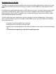
BN9 PC BOARD ASSEMBLY As you can see this is a fairly simple and straightforward project, but be careful! Don’t rush and improperly mount a part or leave long lead lengths on components. As all good technicians and experimenters know, parts must be mounted flush to the PC board. Not only for mechanical strength and looks, but also to prevent oscillation problems by long lead lengths acting as small antennas. Just follow the assembly instructions carefully and take your time.
ASSEMBLY OF THE BN9 ❒ 1. Orient the circuit board as shown in the Parts Layout Diagram. ❒ 2. Install U1, the LM-380 IC into the PC board, making sure that all 14 pins are in their proper holes. Also note in which direction the notch is oriented in the Parts Layout Diagram. Make sure U1 is mounted in the same way when you solder it in. To make soldering easier, flip the board over so the pins are facing up. This way the part can be soldered flush to the board with ease.
The following electrolytic capacitors are polarized and must be inserted with proper orientation to the polarity markings. Usually the capacitors are marked with a side stripe to indicate the negative (-) pin or rarely a plus symbol to indicate the plus side. NOTE: The Parts Layout Diagram designates the holes where the positive (+) leads go. ❒ 8. Install C3, the 4.7µF or 10µF electrolytic capacitor. ❒ 9. Install C4, the 4.7µF or 10µF electrolytic capacitor. ❒ 10. Install C6, the 4.
INITIAL TESTS: ❒ 1. Connect up 8 to 15 volts of DC power. For simplicity use a red wire for positive (+) and a black wire for negative (-). Wait! check polarity before switching on the supply. ❒ 2. Connect any speaker ranging from an impedance of 3 ohms to 45 ohms. Speakers in the 4 to 8 ohm region are best suited for this kit and will yield the greatest power. Make sure the speaker wires are in the correct holes! ❒ 3.
MICROPHONE AND AUDIO INPUT CONSIDERATION You may choose almost any transducer to convert sound into an electrical signal for your BN9. Some of the transducers are as follows; ceramic, crystal, dynamic, or even another speaker! You may also use audio from any other source as well (other than a zillion watt per channel power amp!) GAIN CONSIDERATIONS In applications where you don't need so much gain, such as amplifying earphone outputs, you may wish to omit the pre-amplifier stage.
Problem: Output drops out and then builds up again each time volume control is advanced. Solution: You are running with too much input power. Change circuit for lower gain operation or reduce input level. Problem: Very strong AC hum. Solution: Input may not be shielded or connected properly. Check all of your connections to make sure you have shielded wire and connections are grounded. Problem: Still humming or slight annoying AC hum. Solution: Try using a battery or regulated power supply.
Solution: Motorboating is a sound like the “putt-putt-putt” of a two cycle motor boat. While it may be a novel idea for a simple kit, it’s not exactly what we have in mind here. This is usually noticed at higher audio levels due to the power drawn from the power source. The power source (such as a battery) can’t quite deliver the power needed during a peak, so the voltage “sags” in response. When the voltage “sags”, it allows the power source to come back up again, along with another audio peak.
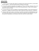
BN9 APPLICATION IDEAS: 1. High sensitivity listening device Components required: • Small microphone such as RAMSEY MC1, mini-electret mike. • 5K to 100K potentiometer for volume control. • 10K resistor (brown-black-orange) • .01uf Ceramic capacitor NOTE: To make a full-performance “big ear” listening system, use a snow coaster or large plastic popcorn bowl. Mount the microphone in the center of the “focal-point” of the parabolic bowl.
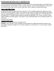
2. Intercom Components required: • DPDT switch (momentary most practical) • Two 8 ohm speakers • Your choice of enclosures IN Remote OUT Low gain BN-9 3. Mini public address amplifier Components required: • 8 Ohm PA speaker or horn speaker • 5K to 100K Potentiometer • Electret microphone or other microphone • 10K resistor for microphone • .
IN OUT Horn Speaker High Gain BN-9 4.
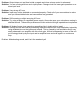
5. Signal Tracer Test Probe Components required: • .01uF Ceramic capacitor rated at at least 200V for tube circuits • 5K to 100K Potentiometer • Shielded test probe with ground clip • 8 ohm speaker or earphone P ro b e 200V IN OU T OTHER APPLICATIONS With a little ingenuity you can use the preceding setups to custom design your own system. The BN9, being simple to assemble and operate, is an ideal choice for circuit add-ons.
The Ramsey Kit Warranty Please read carefully BEFORE calling or writing in about your kit. Most problems can be solved without contacting the factory. Notice that this is not a "fine print" warranty. We want you to understand your rights and ours too! All Ramsey kits will work if assembled properly. The very fact that your kit includes this new manual is your assurance that a team of knowledgeable people have field-tested several "copies" of this kit straight from the Ramsey Inventory.
RAMSEY TRANSMITTER KITS · FM10, FM25B FM Stereo Transmitters · MR6 Model Rocket Tracking Transmitter · AM1, AM25 AM Transmitters RAMSEY RECEIVER KITS · FR1 FM Broadcast Receiver · AR1 Aircraft Band Receiver · SR2 Shortwave Receiver · AA7 Active Antenna · SC1 Shortwave Converter RAMSEY AMATEUR RADIO KITS · DDF1 Doppler Direction Finder · HR Series HF All Mode Receivers · QRP Series HF CW Transmitters · CW700 Micro Memory CW Keyer · CPO3 Code Practice Oscillator · QRP Power Amplifiers RAMSEY MINI-KITS Many o