
All band HF, VHF, UHF Active Antenna Model AA7 Quick Reference Guide


AA7 • 7
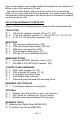
Needle Nose Pliers (RS64-1844)
Small Diagonal Cutters (RS64-1845)
ADDITIONAL SUGGESTED ITEMS
Soldering Iron Holder/Cleaner (RS-64-2078)
Holder for PC Board/Parts (RS64-2094)
Desoldering Braid (RS-2090)
ASSEMBLY INSTRUCTIONS
The following assembly steps are given in accord with the LEARN-AS-
YOU-BUILD philosophy for Ramsey Kits. To the extent that is reasonably
possible, parts are installed in the order of signal flow as depicted on the
schematic diagram, with some discussion of the components whenever
useful.
Because the AA7 is of great interest to people who simply enjoy shortwave
listening and VHF monitoring, experienced ham operators should understand
that our instructions are addressed to people for whom this may be their very
first electronic kit project.
First Assembly Steps
Perform all assembly on a suitable surface which will not be damaged by
hot solder. A cardboard box, cut so that it is flat tends to work well if you do
not have such a surface conveniently available. Always use caution
operating and storing a hot soldering iron. We like to live under a nifty motto
here at Ramsey that we think you will agree with (or will come to agree
with!). “A hot soldering iron looks just the same as a cold soldering iron.”
Trust me... it’s true.
Since you may appreciate some "warm-up" soldering practice as well as a
chance to put some "landmarks" on the AA7 PC-board, we first will install
some "hardware" components, to make the up-down, left-right orientation of
the PC board as clear as possible.
In ALL of the following instruction steps, our word "INSTALL" means to do
the following:
• Insert the part, oriented correctly, into its correct holes in the PC-board.
• If helpful, gently BEND the part's wire leads or tabs to hold it into place,
with the body of the part snugly against the top side ("component side")
of the PC-board. The top side is the side that does not contain metal
traces, but does have an outline of each part printed on it.