“SPEEDY” PERSONAL SPEED RADAR KIT Ramsey Electronics Model No. SG7 YOU BE THE COP! “CLOCK” CARS, BIKES, PLANES, HORSES, JOGGERS, VIRTUALLY ANYTHING THAT MOVES! WORKS ON THE SAME PRINCIPLE AS POLICE UNITS COSTING THOUSANDS MORE. IDEAL FOR LEARNING AND TEACHING RADAR THEORY. • Direct readout in Miles, Kilometers or Feet per second • Operates on 12 volts DC • 1/4 mile range with average size car • Better than 2 miles per hour accuracy, reads to over 200 MPH • Operates on 2.
RAMSEY TRANSMITTER KITS • FM100B Professional FM Stereo Transmitter • FM25B Synthesized Stereo FM Transmitter • MR6 Model Rocket Tracking Transmitter • TV6 Television Transmitter RAMSEY RECEIVER KITS • FR1 FM Broadcast Receiver • AR1 Aircraft Band Receiver • SR2 Shortwave Receiver • SC1 Shortwave Converter RAMSEY HOBBY KITS • SG7 Personal Speed Radar • SS70A Speech Scrambler • BS1 “Bullshooter” Digital Voice Storage Unit • AVS10 Automatic Sequential Video Switcher • WCT20 Cable Wizard Cable Tracer • LC1 Ind
Ramsey Publication No. MSG7 Price $5.00 KIT ASSEMBLY AND INSTRUCTION MANUAL FOR SG7 PERSONAL SPEED RADAR TABLE OF CONTENTS Work involved in building the SG7........ 4 Doppler description .............................. 5 Parts list ............................................... 7 Signal cable assembly ......................... 9 Power supply notes ............................ 10 LED schematic diagram ..................... 12 LED unit PC layout ............................. 13 Assembling the LED unit .....
PLEASE, PLEASE READ THIS! THANK YOU for purchasing the SG7 Speedy Radar Gun. This is a kit project that we're especially proud of. We've packed a lot of value into it, and we know you have paid good money for it and that you sure do expect it to work. Speedy will be a very satisfying project for you - IF you are willing to follow our directions carefully. This is definitely not one of those kits where you can expect to just put some parts on a board and tinker as you go along.
soldered in place very easily, so long as its creases are formed carefully. The oscillator board, enclosed in its tin shield, is soldered to a metal can assembly that has been prepared with TLC (Tender Loving Care). You will find that both the oscillator shield and the can will solder very easily. After all, tin is a major ingredient of solder. A 1.
A Doppler radar measures the velocity of a moving object by doing something useful with the detected shift in carrier frequency of the returned or "echo" signal. The shift is proportionate to the speed of the object as it approaches or moves away. An easy way to understand what a Doppler radar actually does is to think about how one of our other kits actually works- the much simpler but fun and practical MD-3 Microwave Motion Detector or "intrusion Alarm".
PARTS LIST: LED SPEED READOUT PC BOARD: CAPACITORS 1 100pF capacitor (marked 100 or 101) (C16) 1 2200pF disc capacitor (marked .0022 or 2200 or 222) (C5) 1 .005µF capacitor (marked .005 or 5000 or 502) (C1) 2 .001µF capacitors (marked .001 or 102) (C3,C11) 6 .01µF capacitors (marked .01 or 103 or 10nf) (C4,13,15,17,18,19) 2 .047 or .05µF capacitors (marked .047 or 473, .05 marked .
OTHER COMPONENTS 1 SG7 printed circuit board 1 Case kit 1 Miniature stereo (signal) jack (J1) 4 case screws 1 Subminiature phone jack (J2) 4 3/8" threaded standoffs 1 DC coaxial power jack (J3) 8 #4 screws 1 Stereo (signal) plug 1 front panel decal 1 power plug (may include wire) 1 5 feet of 2 conductive shielded hookup wire MICROWAVE OSCILLATOR PC BOARD: CAPACITORS 3 .01µF disc capacitor (marked .01 or b103 or 10nf) (C1,2,6) 1 .
ASSEMBLING THE 2-CONDUCTOR SIGNAL CABLE: Your SG7 kit includes two plugs and a length of 2-conductor shielded cable for making the custom cable connect the Speed Readout Unit to the Microstrip Oscillator. Assembly of this cable is a good warm-up job and its nice to have it ready when it's time to do our serious testing. While making up this cable will be a very obvious procedure for many builders, here are some hints for those who will appreciate them: 1.
6. Use needle-nose pliers to close both strain-relief clamps, but be sure you don't crush through the wire insulation! 7. Install both plug shells and check all connections with a VOM or continuity tester before using the cable. MORE SG7 CABLE OPTIONS: The cable kit supplied with your SG7 will handle the majority of typical applications. However, "non-typical" applications can be even more fun and useful.
Your battery power supply can be enclosed in whatever style of pack that suits your needs, tastes and budget. Discount-priced camera accessory bags are ideal for this purpose. Consider using a case with an extra pouch for storing the SG7 Speed Readout Unit, earphone, cables, etc. It is entirely up to you whether to install a switch in the battery cable. A NOTE ABOUT TOOLS FOR THIS KIT: For easiest assembly of the SG7, we suggest this listing of tools to have on hand, borrow or buy: A.
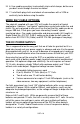
LED SCHEMATIC DIAGRAM: SG7• 12
LED PARTS LAYOUT DIAGRAM: SG7• 13
BUILDING THE LED SPEED READOUT UNIT: There are FOUR basic considerations in assembling this PC board: 1. Good, basic PC board construction technique. 2. Avoiding or repairing "solder bridges" on 110 different IC or LED display solder points. 3. A smooth fit of the PC board into its custom-designed case, which requires observing assembly directions and understanding the design of the completed unit. Mostly, this calls for the horizontal installation of electrolytic capacitors. 4.
Step 1: Install U1, 14-pin IC, type LM324. Step 2: Install U2, 14-pin IC, type MC14093 (or CD4093). Step 3: Install U3, 14-pin IC, type 4011. Step 4: Install U4, 16-pin IC, type 4518. Step 5: Install U5, 16-pin IC, type 4511. Step 6: Install U6, 16-pin IC, type 4511. IN THE FOLLOWING STEPS, BE SURE THAT THE ORIENTATION DOTS ON THE LED DISPLAYS ARE POSITIONED AS SHOWN ON THE PC BOARD DRAWING!!! Step 7: Install U7, 7-segment LED display. Step 8: Install U8, 7-segment LED display.
14. Install R6, 1 megohm resistor [brown-black-green]. 15. Install R8, 22K ohm resistor [red-red-orange]. 16. Install R27, 220 ohm resistor [red-red-brown]. 17. Install R9, 22K ohm resistor [red-red-orange]. 18a. Examine the two small potentiometers. While they may be identical in appearance, one is stamped 2.2K (R10, Sensitivity Control), and the other is 10K (Calibration Control).
• If U2 is marked "CD4093", then C20 is 22µF electrolytic capacitor. • If U2 is marked "MC14093", the C20 is 33µF electrolytic capacitor. 37b. Install the correct value for C20 per 37a, observe correct polarity. PROGRESS SUMMARY: By now, you have installed the majority of the individual components for the LED Speed Readout Unit. As you can see on the PC board drawings, installation of a large number of jumper wires is required, and their correct connections are seen most clearly in relation to the ICs.
40. Install R24, 220 ohm resistor [red-red-brown]. 41. Install C19, .01µF disc capacitor (marked .01 or 103 or 10nF). 42. Install C16, 100pF disc capacitor (marked 100 or 101). 43. Install R17, 10K ohm resistor [brown-black-orange]. 44. Install R20, 47K ohm resistor [yellow-violet-orange]. 45. Install C15, .01µF disc capacitor (marked .01 or 103 or 10nF). 46. Install R18, 47K ohm resistor [yellow-violet-orange]. 47. Install D1, the small 1N4148 diode.
side. Do a trial positioning in order to understand how the jack is connected. Notice that the edges of the two jack lugs will be perpendicular to the PC board surface. 57b. The PC board areas to which the two outer jack lugs are to be soldered may be covered with a green coating called solder mask. If so, use a knife blade to gently scrape away the mask from the area shown down to bare shiny copper. 57c. "Tin" both copper areas with solder.
panel decal, it may be sprayed with a fast-drying clear acrylic or urethane finish. Be sure to mask off the red lens window to avoid covering it with spray. BUILDING THE SG7 MICROWAVE OSCILLATOR: Before beginning, study the PC board layout diagram on the next page. Some parts are mounted completely on the top side while others have one lead soldered to a strip on top and another passing through a hole for soldering on the solid tinned side.
MICROWAVE OSCILLATOR PARTS LAYOUT: 1.
1a. Disc capacitors C1 and C2, .01µF (marked .01 or 103 or 10nF) are installed as a single operation. Notice that each has one lead going through the board and another to be soldered to a trace on the top. Also notice that the ground pin of the signal jack will be soldered to AA. Therefore the wire leads of C1 and C2 provide the ONLY connection between AA and the main ground plane and must be soldered on BOTH sides of the board. 1b.
8. Install D1, the 1N4148 diode. Be sure not to confuse it with the special 1SS99 hot carrier diode which is smaller and has black and blue color bands. Be sure that the banded (cathode) end is oriented correctly. 9. Install Q1, 2N3904 transistor. The flat side must face D1, and the lead wires of the transistor must be soldered on BOTH sides of the PC board. Pre-form the leads and it will sit in position very nicely for soldering. 10. Install R3, 1K ohms [brown-black-red]. 11.
is important for several reasons. If it is damaged, your project will be on hold until you can get a replacement from us. Also, lead wires MUST be kept as short as possible - and its cathode end is soldered very near the SMT chip capacitor. Its glass body is very fragile, so be careful! 17b. After considering the concerns in step 17a., carefully install diode D2, making sure the banded (cathode) end is toward C7. CONGRATULATIONS! You have completed construction of a 2.6GHz. microstrip oscillator.
the 1.1" antenna extending neatly through the pre-cut notch. While the first one or two bends can be made using a small hobby vise, the process will show you why you need some kind of rigid straight edge to complete the job. IMPORTANT: While the metal is easy to bend and you are strong and healthy, your two thumbs are NOT a smooth-metal bending tool. A pair of solid, even forming edges are required for a straight bend.
6. Make a final check for straightness and antenna positioning. 7. Solder all 4 sides of the oscillator assembly to the can. A solid solder seam is as important for range as it is for mechanical strength. The solder must run fully along all edges where the oscillator box touches the can. Flow enough solder to fill in any can ribbing under the oscillator box. 8. Do not paint the oscillator assembly until you are positive that your SG7 is functioning as specified.
MAKING THE METAL RADAR ANTENNA HOUSING: "What??? I paid all this money for an electronics kit and I'm now expected to solder some tin cans?" Leaving this particular phase of building Speedy to your own craftsmanship is the only possible way we can bring you this kit project so inexpensively.
3. Line up the main seams of both cans in a straight line. (This is only for a better-looking job.) 4. With the two cans perfectly joined together, use several strips of masking or electrical tape to hold the rims steady. 5. In the centers of the exposed non-taped areas, make good, solid solder joints at least a half inch long. 6. Remove all tape and re-clean the areas to which the tape had adhered. 7. Patiently solder a solid seam around the entire perimeter of the joined can rims. 8.
TESTING AND CALIBRATION: 1. Connect an earphone to J2, using a subminiature plug or adapter. 2. Connect the counter and oscillator units together with the shielded 3conductor cable already assembled. 3. While listening to the earphone, plug in the 12 volts DC cord. The LED displays should light right away. After a few seconds, you should hear a steady AC buzz in the earphone. Next, if you wave your hand in front of the open end of the antenna "can", you should hear a rapid series of clicks.
FINAL CALIBRATION: To put it simply, the SG7 is calibrated by adjusting the control while pointing the antenna unit at a vehicle traveling at a steady, known speed. Obviously, the accuracy of the radar unit depends on the steadiness of the test drive and the accuracy of the vehicle's speedometer. To verify speedometer accuracy, use a stopwatch to time how long it takes the vehicle to travel a given distance and carry out the appropriate calculations.
TROUBLESHOOTING HINTS 1. Instructions are provided for checking voltages on the microstrip oscillator board before soldering the cover on. 2. If operation is erratic, check the cable assembly, and be sure that you followed the instructions for trimming away the plastic legs on BOTH 3conductor jacks. If this is not done, reliable solder connections are difficult to make. 3.
MODIFICATIONS: We are always interested in any customer reports and suggestions on adaptions of the basic SG7 design. We do not recommend any circuit modifications and ask that you remember that modifications make your kit ineligible for factory repair. Our technicians are not able to get into telephone discussions of possible modification ideas, but we're always glad to reply by fax or mail to a few clearly-stated "yes-no" questions.
USING THE SG7: The SG7 Personal Speed Radar is suitable for any application which comes within its specified range and accuracy. It was designed to be fun and educational and we assume that you will find your own uses for it, whether for sporting events, as a science fair project, scout troop project, or school/ neighborhood volunteer safety patrols. Remember that the purpose of ANY speed radar is to provide a speed indication that falls within reasonable tolerances.
The Ramsey Kit Warranty Please read carefully BEFORE calling or writing in about your kit. Most problems can be solved without contacting the factory. Notice that this is not a "fine print" warranty. We want you to understand your rights and ours too! All Ramsey kits will work if assembled properly. The very fact that your kit includes this new manual is your assurance that a team of knowledgeable people have field-tested several "copies" of this kit straight from the Ramsey Inventory.
3. FACTORY REPAIR OF ASSEMBLED KITS: To qualify for Ramsey Electronics factory repair, kits MUST: 1. NOT be assembled with acid core solder or flux. 2. NOT be modified in any manner. 3. BE returned in fully-assembled form, not partially assembled. 4. BE accompanied by the proper repair fee. No repair will be undertaken until we have received the MINIMUM repair fee (1 hour labor) of $50.00, or authorization to charge it to your credit card account. 5.
SG7 PERSONAL SPEED RADAR KIT Quick Reference Page Guide Introduction to the SG7 ........................ 4 Parts list ............................................... 7 LED schematic diagram ..................... 12 LED unit PC layout ............................. 13 Assembling the LED unit .................... 14 Assembling the microwave unit .......... 20 Microwave unit PC layout ................... 21 Microwave unit PC board ................... 26 Testing and calibration .......................