
Instruction manual


SG7• 14
BUILDING THE LED SPEED READOUT UNIT:
There are FOUR basic considerations in assembling this PC board:
1. Good, basic PC board construction technique.
2. Avoiding or repairing "solder bridges" on 110 different IC or LED display
solder points.
3. A smooth fit of the PC board into its custom-designed case, which requires
observing assembly directions and understanding the design of the
completed unit. Mostly, this calls for the horizontal installation of electrolytic
capacitors.
4. Planning for and understanding the need for a large number of "jumper"
wires in this circuit board design.
In general, assembly of this PC board is quite conventional, but we'll show you
special steps for a solid, well-fitting installation of the 12-volt power jack.
We encourage you to follow our suggested order of assembly.
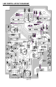
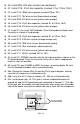
PC BOARD ASSEMBLY:
1. Install J2, the audio monitoring jack. Solder all three points. It's easy and
a good start.
2a. Examine J1, the 3-conductor jack for interconnection with the
microwave oscillator or "radar gun" unit of this project. The little plastic
"legs" on the bottom of the jack should be removed, which is easy with wire
nippers or even an emery board. We suggest using a touch of glue on the
underside of the smoothed-out jack body. The purpose of this extra TLC is
to make J2 as rugged as possible for repeated plugging in/out.
2b. Install 3-conductor jack J1 per step 2a.
3. Installation of ICs or IC sockets. Using good technique, the 6 ICs can be
safely and easily soldered directly to the PC board. If you prefer to use
sockets, you will need three 14-pin sockets. Sockets need to be treated
with the same careful attention as the ICs themselves, both in soldering
and IC insertion. For all socket or IC installations, press the device in its
holes so that the body is flush against the board. While holding it in place,
slightly bend the pins in the four corners to hold it in place for soldering.
Use good lighting and a very clean solder tip. Take short breaks as needed
so that the quality of your work remains consistent and solder bridges are
avoided.
IN THE FOLLOWING STEPS, BE SURE THAT THE NOTCHED, DOTTED OR
BANDED END OF EACH IC IS ORIENTED AS SHOWN ON THE PC
DRAWING!!!