
Instruction manual


SG7• 31
TROUBLESHOOTING HINTS
1. Instructions are provided for checking voltages on the microstrip oscillator
board before soldering the cover on.
2. If operation is erratic, check the cable assembly, and be sure that you
followed the instructions for trimming away the plastic legs on BOTH 3-
conductor jacks. If this is not done, reliable solder connections are difficult
to make.
3. If you don't hear anything in the earphone, check the earphone itself, the
plug or adapter for J2, the orientation of the NPN transistor and the
polarity of C10 and C12.
4. If you experience other problems in the counter display unit, please
recheck the following in this order:
a. Correct orientation of ICs and 7- segment displays.
b. If sockets were used, check for bent IC pins.
c. Correct polarity of all electrolytic capacitors.
d. Correct orientation of D1 and D2.
e. Possibility of solder bridges, especially at ICs.
f. Forgotten solder joints.
g. Correct resistor values.
h. All jumper wires installed.
5. Common causes of major trouble:
a. Antenna shorted to can.
b. Defective 3-conductor cable assembly.
c. Reverse polarity on power cord.
d. Solder bridges.
e. Reversed diodes (BOTH PC boards).
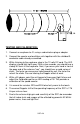
6. If you experience poor range, check:
a. Correct length of antenna wire probe
b. SHORT lead length on the 1SS99 diode
c. Proper adjustment of the gain control pot
d. Clean, solid 12 volt power source
e. Be sure outside sources are not interfering with the SG7