Ramsey Electronics Model No. PG13 Have you ever wanted to play with a controlled substance? Now you can! It is called plasma, and it is easily generated by this nifty high voltage kit. This is the same though more powerful supply that is used in Plasma Balls and neon art, and can be used for all sorts of high voltage experiments! Turn a standard light bulb into a plasma sphere! • • • Perfect for driving a Jacob’s ladder.
RAMSEY TRANSMITTER KITS • FM100B Professional FM Stereo Transmitter • FM25B Synthesized Stereo Transmitter • AM1, AM25 AM Transmitters • TV6 Television Transmitter RAMSEY RECEIVER KITS • FR1 FM Broadcast Receiver • AR1 Aircraft Band Receiver • SR2 Shortwave Receiver • AA7 Active Antenna • SC1 Shortwave Converter RAMSEY HOBBY KITS • SG7 Personal Speed Radar • SS70A Speech Scrambler • SP1 Speakerphone • WCT20 Wizard Cable Tracer • ECG1 Heart Monitor • LABC1 Lead Acid Battery Charger • IG7 Ion Generator • CT25
Ramsey Publication No. MPG13 Price $10.00 KIT ASSEMBLY AND INSTRUCTION MANUAL FOR PG13 PLASMA GENERATOR KIT TABLE OF CONTENTS Safety Guidelines .................................4 History ...................................................9 Circuit Operation .................................12 Learn As You Build .............................16 Parts List .............................................18 Assembly .............................................19 Schematic........................................
SAFETY GUIDELINES FOR HIGH VOLTAGE AND/OR LINE POWERED EQUIPMENT Author: Samuel M. Goldwasser Corrections/suggestions: sam@stdavids.picker.com Copyright (c) 1994, 1995, 1996, 1997, 1998 All Rights Reserved Reproduction of this document in whole or in part is permitted if both of the following conditions are satisfied: 1. This notice is included in its entirety at the beginning. 2. There is no charge except to cover the costs of copying.
connected devices like Tesla Coils, Jacobs Ladders, plasma spheres, gigawatt lasers, fusion generators, and other popular hobby type projects. In addition read the relevant sections of the document for your particular equipment. Specific safety considerations have been included where appropriate. Safety guidelines These guidelines are to protect you from potentially deadly electrical shock hazards as well as the equipment from accidental damage.
• • • • • • • greater resistor of 100-500 ohms/V approximate value (e.g., for a 200 V capacitor, use a 20K-100K ohm resistor). Monitor while discharging and/ or verify that there is no residual charge with a suitable voltmeter. In a TV or monitor, if you are removing the high voltage connection to the CRT (to replace the flyback transformer for example) first discharge the CRT contact (under the insulating cup at the end of the fat red wire).
• • materials with a high resistance path between you and the chassis (greater than 100K ohms). Never use metallic conductors as you would then become an excellent path to ground for line current or risk amputating your hand at the wrist when you accidentally contacted that 1000 A welder supply! Don't attempt repair work when you are tired. Not only will you be more careless, but your primary diagnostic tool - deductive reasoning - will not be operating at full capacity.
voltage. This is only true if you do not modify the kit in any way. Here is the reason why, which is very interesting: So here is the abridged answer to your question: Sodium channels are responsible for the initiation and propagation of action potentials. Action potentials are those electrical signals that carry messages throughout the body whether they be neuronal or cardiac in nature. Sodium channels go through a basic gating scheme.
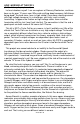
HOW I ARRIVED AT THE PG13. (A little history, if you please!) Let me introduce myself. I am an engineer at Ramsey Electronics, and have been so for over 12 years now. Who said anything about company faithfulness being dead? Anyhow since I was in high school I have been messing around with high voltage, because it is a challenge, a bit risky, and is simply fascinating. I suppose the fixation on high voltage stems from an earlier fascination with fire, but I won’t get into that.
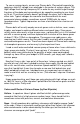
To see an aurora closely, we can use Plasma balls. Plasma balls operate by applying a high AC voltage to an electrode in the center of a glass sphere. This high voltage must be high frequency AC in order for any current to get through the glass of the globe and surrounding air by capacitive coupling to your hand or the air. The current actually doesn’t go through the glass, but is induced on either side.
Carbon Dioxide - Glows a whitish or blue-white color. It is probably good to have no direct contact with metal electrodes for long life with gases that are not completely inert. Carbon dioxide probably requires more voltage than the noble gases. Generally, gases and vapors with monoatomic molecules work with less voltage than others. Nitrogen - Streamers are usually a whitish or grayish pink or light orange. The color may be more gray or lavender at very low currents.
CIRCUIT OPERATION What is going on with this board may look simple at first, but it is actually quite a difficult design to get working properly and reliably. A lot has to be considered with magnetics when dealing with high voltage, high frequency transformers. Unlike power transformers like the one powering the entire kit, high voltage transformers have a “sweet spot”, or a resonant frequency where they operate the most efficiently.
We have included two 0.25mm spacers for you to do experiments with. Since the transformer is specific about its “sweet spot”, we couldn’t run the drive circuit directly from a pulse width modulator circuit (PWM). We may have been able to tune it up really close while there was no load applied, but as soon as we would draw a spark, the frequency would change, and our output would drop considerably.
Once saturation occurs, the flux stops increasing in the core, and the current that was induced in the feedback winding abruptly halts and reverses direction due to a “ringing” effect. This reversal in current direction then turns off Q3 and begins to turn on Q4, which quickly ramps up the flux in the core now heading in the other direction. (Fig 2). This cycle goes back and forth continuously until power is removed. To control the output voltage we can simply adjust our driving voltage.
transformer, or under full load. In the case of the transformer we will be supplying, it is rated for 3 amps. We idle at 0.5 amps. This means the wall transformer will actually put out much more voltage under this low load. In fact after measuring this I found the rectified DC to be close to 19.2 VDC, which is 17% higher than we would expect. Using this 19.2VDC, we can now find what our output of the secondary will be. Since we are operating push-pull, 19.
RAMSEY “LEARN-AS-YOU-BUILD” ASSEMBLY STRATEGY Be sure to read through all of the steps, and check the boxes as you go to be sure you didn't miss any important steps. Although you may be in a hurry to see results, before you switch on the power check all wiring and capacitors for proper orientation. Also check the board for any possible solder shorts, and/or cold solder joints.
We sincerely hope you put this kit together in a professional manner. This project will not work as well as you wished if you don’t follow good assembly techniques, and follow all instructions. No matter how clear we may think our manual is, if you have any questions give us a call at the factory instead of going it alone; we will be happy to help you with any problems. As good engineering and kit building practice we want to mount the parts AS LOW AS POSSIBLE to the board.
RAMSEY PG13 PARTS LIST Semiconductors 4 1N5408 3 AMP Rectifier diodes (D2,3,4,5) 1 RED LED (D1) 2 TIP31C 100V Bipolar NPN Power Transistors (Q1,2) Resistors 1 100 ohm resistor (brown-black-brown) (R5) 1 1K ohm resistor (brown-black-red) (R1) <- Small Size 1 1K ohm 1/2 Watt resistor (brown-black-red) (R2) <- Large Size 2 30 ohm 1 Watt resistors (brown color, marked 30 Ω) (R3,4) Capacitors 1 0.1uF Ceramic capacitor (marked 104) (C1) 2 0.
ASSEMBLY We will begin with the board oriented with the power switch mounting position towards you. This is just to keep our parts locating task simple. 1. Install S1, the power switch. Solder all six leads. 2. Install R2, the larger 1K ohm 1/2 watt resistor (brown-black-red). 3. Install R5, 100 ohm resistor (brown-black-brown) . 4. Install C1, the 0.1uF ceramic capacitor (marked 104). Note that this part looks more like a disk than the other 0.1uF Mylar capacitors. 5.
17. Install D1, the red LED. 18. Now here comes a really critical install. Install C3, one of the 3300 or 4700uF electrolytic capacitors. PAY CLOSE ATTENTION TO ORIENTATION! Usually the negative side of the capacitor is indicated with a stripe and large negative (-) symbols. This is the side that will mount away from the positive indicator we show on our PC boards. Hook these babies up the wrong way and you are in for a catastrophic failure! 19.
the other half. 33. Install the other half of the U core. 34. Locate the plastic tubing for the U core clamp. Cut the tubing in half and slide a piece over each end of the clamp. Then use the U core clamp over the top center of the transformer. The clamp cannot be installed along the side of the U core pieces. 35. Install XFMR1, the high voltage transformer (marked CHT-0126G). Make sure all of the wires are through the appropriate holes before soldering any of the wires! 36.
41. Place the metal ball terminal in whatever holder you’ve chosen. Heat a spot on the ball with your soldering iron and hold solder on it until the ball is hot enough to melt the solder. Once you have a good size blob of melted solder on the ball, take the nail and place the head of the nail in the blob of solder. (No, you don’t need three hands; simply use the hand that was holding the solder to hold the nail!) You’ll want to hold the nail with needle nose pliers, as it may become hot.
1. Check all of your electrolytic capacitors for orientation. I can’t stress this enough! 2. Then check your diodes. Install one the wrong way and your power transformer could be shorted through only two diodes. I guarantee your transformer and diodes would not like this. 3. Check your solder connections to make sure they look nice and clean, with no questionable connections. 4. Check all hardware for a nice mechanical fit, and that the heatsinks are securely attached to the transistors.
PG13 SCHEMATIC DIAGRAM PG13 • 24
POWER SUPPLY If you have purchased the wall transformer for the PG13, note that it may have a center tap that we won’t use. The center tap is the black lead, and we will simply cut it off. Use the other two leads in the holes marked AC1 and AC2. Do NOT install the center tap into the hole marked GND, as we will connect this to actual earth ground. The transformer may come with a screw that you may use for the center mounting hole of the wall plug to hold the plug securely in the socket.
USING YOUR OWN POWER SUPPLY AC Sources: You will need to use an AC transformer capable of 3 AMPS in the range of 5VAC to 16VAC. 14VAC will give you the best performance and balance between temperature and voltage output. You do not need to use a center tap. Connect either side of your AC transformer to the lugs marked AC1 and AC2 on J1. Then connect a wire between the ground lug and a good earth ground, like the ground pin of your AC line cord that you use to power the transformer (usually green).
Many power supplies have this, so just tie a wire between the terminal and earth ground on your power supply. Otherwise use the center screw on a wall plug face plate. Cool Pictures These two pictures were taken with the camera on a tripod so that the shutter could be left open for 20 seconds. The room was kept very dark while taking the picture.
TESTING THE PG13 This, unfortunately, will be a process of turning on the power, and hoping all goes well! If you have a multimeter with a current reading scale of 3 amps or greater (usually 10 amps), you can connect it in series with your power source to monitor supply current while turning the unit on. Meter connections: P.S. - A + If you are using an AC transformer, switch the meter into AC mode, DC for DC.
t F low Cur re n Bring the tip of the screwdriver close to the high voltage terminal, you should see a decent sized spark form at about 1/4” or more away from the terminal, and then be able to stretch it to an inch or more! It is pretty amazing to see that we can draw this significant arc to a piece of metal that is apparently not connected to anything. In reality it is connected to something so I will draw you a few simple diagrams to show you where this current flow is going. Curr ent Flo w 0.
In the case of the neon bulb, it is a little more complicated. Sometimes it may light due to the high electrical and magnetic field around the transformer, and sometimes it may light due to the capacitor formed by the air as the dielectric and the bulb gas and the transformer as the two plates. These effects are interrelated however, so here is the basic principle of the neon bulb circuit and why it lights. Curre nt Fl ow <0.
TROUBLESHOOTING PROBLEM: The LED doesn’t light up. SOLUTION: Not much can go wrong in the circuit that prevents this other than you forgot to turn the circuit breaker back on after fiddling with the wall socket, or you forgot to turn on the AC power. Check all of your connections again. It is quite possible you have a dead short someplace, so you had better check it out without the power applied! Also check diode orientation. PROBLEM: The LED lights, but no high voltage. Also, the neon light will not light.
EXPERIMENTS: Now here comes the fun part, playing with your new toy. You may be surprised at how many cool things you can do with this, especially if you search on the internet for high voltage. These experiments are only for you to get started on. If you have some great ideas, share them with us on the Ramsey Electronics bulletin board at http://www.ramseykits.com WARNING! Be aware that arcs have plenty of heat and energy in a small space.
Corona leakage can be a big problem in high voltage circuitry since any sharp point will lose quite a bit of power to the air. To cure this a manufacturer will coat all possible leakage points with silicone RTV, since it is a good insulator when dry. Corona Motor Now we can put this leakage to work for us. In fact NASA has put this to work for them too, for pushing spacecraft around. When corona is coming off the end of a sharp point, ions are coming off the point at a high rate of speed.
finger. You may need to devise a better method to reduce friction than what you have, but it shouldn’t be too hard. The lower the friction and better the balance, the faster this will go! 9. Power up the PG13. You should see the rotor begin to rotate. If you really did a good job of making it, it can reach some pretty astonishing speeds! Better Corona Motor Here we will use a pattern to cut a piece of thin sheet metal or soda can to the appropriate size.
A Jacob’s Ladder The classic experiment to make an impressive display! We have some current limitations with this high voltage power supply, and we need a lot of current to make a decent Jacob’s Ladder. Because of this we will need to pull some tricks to make the spark move for us. For one, we cannot connect one post to the high voltage and the other one to ground. This loads the supply too much, and it is unable to maintain a healthy spark. Instead you will need an “air” load of a soda bottle of water.
I will admit that this experiment is difficult to reproduce due to the low power involved on the output terminal. If I had added more parts to the kit, then you could draw a hotter spark. The problem is that we also run into other problems too, like power dissipation—the heatsinks would no longer be adequate, and strange oscillation effects caused by the varying load conditions.
Home Brew Plasma Ball I spent quite a while trying to find the “perfect” light bulb just for this purpose and have yet to find one. The best one I have found so far has been a 100 Watt Philips Clear Globe light bulb. It is fairly large, and it ionizes easily. I was able to find this in our local Home Depot, though it had plenty of dust on it, suggesting it isn’t a very popular bulb. The model number is 808472. What you’ll need: • • Some way to hold the light bulb that is non-conductive.
Advanced Plasma Ball I have not tried this yet, so I leave it up to the experimenter to figure this one out, but these are some ideas to play with. It involves using special gas, possibly a vacuum pump, and some materials that may be difficult to get a hold of. Anyway, here are my plans, and if you get it to work, post your findings on the Ramsey Electronics BBS. What you’ll need: • • • • • • • Glass Dome used for lighting. I have seen these on driveway lights up to about 10 inches in diameter.
6. Drill two small holes somewhere within the dome circle on the vinyl. This will be where you insert and remove special gases through your tube fixtures. These MUST be sealed well. You will need to choose your hole sizes according to the fixtures used. 7. Install the hose fixtures in the vinyl and seal them in place. Let all glue/ goop dry. 8. Lay a heavy bead of sealant into the route you carved in the vinyl. 9.
Conductive Glass If you’ve always thought glass was a good insulator, guess again! When glass gets good and hot, it becomes more and more conductive. There are several ways to test this, but here is the best one I have seen. What you will need: • • • • Glass rod (1/4 inch diameter). Some wire. Two nails Something to hold the two nails in place that is non-conductive. What to do: 1. Turn off the power. 2. Use the wire and nails to make a rudimentary spark gap in the air.
More Experiments: Go to the Ramsey Electronics web site, and go to the bulletin board under hobby kits. We will have a forum on the Plasma Generator kits where people will share design ideas and experiments.
Component Placement PG13 • 42
The Ramsey Kit Warranty Please read carefully BEFORE calling or writing in about your kit. Most problems can be solved without contacting the factory. Notice that this is not a "fine print" warranty. We want you to understand your rights and ours too! All Ramsey kits will work if assembled properly. The very fact that your kit includes this new manual is your assurance that a team of knowledgeable people have field-tested several "copies" of this kit straight from the Ramsey Inventory.
PG13 PLASMA GENERATOR KIT Quick Reference Page Guide Safety Guidelines ................................. 4 History ................................................... 9 Circuit Operation ................................. 12 Learn As You Build ............................. 16 Parts List ............................................. 18 Assembly ............................................ 19 Schematic ........................................... 24 Power Supply......................................