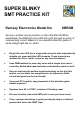
SUPER BLINKY SMT PRACTICE KIT Ramsey Electronics Model No. SBRGB Get your surface mount practice on this nifty little kit! When assembled, the RGB full color LED will cycle through an array of mesmerizing colors! Makes for an excellent attention getter or name badge light like no other! • Bright full-color LED (not a single white element) with independently drivable red, green and blue LED elements.
PARTIAL LIST OF AVAILABLE KITS RAMSEY TRANSMITTER KITS • FM100 Professional FM Stereo Transmitter • FM25B Synthesized Stereo Transmitter • AM1, AM25 AM Transmitters • TV6 Television Transmitter RAMSEY RECEIVER KITS • FR1 FM Broadcast Receiver • AR1 Aircraft Band Receiver • SR2 Shortwave Receiver • AA7 Active Antenna • SC1 Shortwave Converter RAMSEY HOBBY KITS • SG7 Personal Speed Radar • SS70A Speech Scrambler • SP1 Speakerphone • WCT20 Wizard Cable Tracer • ECG1 Heart Monitor • LABC1 Lead Acid Battery Char
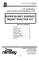
Ramsey Publication No. MSBRGB Price $5.00 KIT ASSEMBLY AND INSTRUCTION MANUAL FOR SUPER BLINKY SURFACE MOUNT PRACTICE KIT TABLE OF CONTENTS Introduction ...................................... 4 Circuit Description ............................ 5 Parts List .......................................... 9 Assembly Steps ............................... 10 Using the SBRGB ............................ 16 Project Idea ...................................... 16 Schematic Diagram..........................
INTRODUCTION The Super Blinky was thought up as a way to show off the latest technology in RGB (Red, Green, Blue) color LEDs. These babies have always been tempting to play with in order to see just how many colors they could reproduce. The problem was that the darned RGB LEDs were so expensive (the Boss just about had a heart attack). Some of these LEDs cost more than $19.00 a piece as of the writing of this manual.
CIRCUIT DESCRIPTION In the old days, we used to make things as simple as possible. The original blinky used two transistors, two capacitors and four resistors. This simple circuit is now seen everywhere in blinky kits so we decided to use a new and novel approach with this one. Our new blinky kit requires over 20,000 transistors, three capacitors, five resistors, and a few other parts. The difference is we can make the LED do anything we want, well almost anything.
All that this example code does is to set the Red LED at 50% brightness. If we wanted to change it to 25% brightness, we would change line 2 to: movlw 0x40 ;25% (256/4 = 64 base10 = 40 HEX) Now imagine that we vary the percentage value in real time using a variable rather than a constant of 0x40 (HEX numbering system). On top of this, use a Sine lookup table to produce smooth changes.
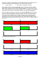
As shown, violet is created mostly by blue with some red. If you own a computer, you can try these shades out by changing your display properties and custom selecting a color. It will allow you to enter color values in Red, Green, and Blue in a range of 0-255 just like the Super Blinky! The timing charts only show a small percentage of the overall PWM waveform. To keep the LEDs from appearing to blink, we have to keep them flashing at a rate faster than our eye can see (at least 30 times a second).
Another interesting point to note is that for this LED to have enough green content to match up with the blue and the red components, two elements were needed! To achieve a good quality white color, we have to provide the proper current from the driver for each color element. Here is the key to the values chosen for resistors R1, R2, and R3. We want 20 mA, 40 mA, and 20 mA in each of the Red, Green, and Blue elements respectively to get a good white when fully on.
PARTS SUPPLIED WITH THE SUPER BLINKY KIT: Note a few extra chip parts included. Capacitors 2 0.1 µF chip capacitor (no marking, usually brown) [C1] 2 1 µF electrolytic surface mount capacitors (Silver, marked 1 µF) [C2,C3].
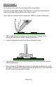
SBRGB ASSEMBLY Use the boxes to check off your progress as you go along. Check all received parts against the Parts list. The parts list describes the various markings that may be found on the kit parts. In the case of a surface mount component, INSTALL means these steps: • Dab a small amount of solder on one pad of the PC board for the component you wish to install. Usually choose pin 1. • Locate the appropriate part from those packed in the kit.
• Use the other hand to re-heat the solder dab to melt it to the component connection. • Let the solder cool and then let go with the tweezers. Inspect orientation and make sure the part is square over the correct pads. Make sure stray solder connections don’t overlap or short across the adjacent pads. • Apply solder to the rest of the pads. • Apply a touch more solder to the initial pad to make sure there is a good solder joint. The rosin core flux will clean the joint and insure stability.
• Nip or "trim" all excess wires extending beyond each solder connection. Take care that wire trimmings do not become lodged in PC board solder connections. Enough said. . . Let's get building! You are going to want to use a VERY clean desk space to assemble your surface mount kit. Drop a resistor into even the smallest amount of clutter and it will disappear like magic. You would swear a magician was hovering over your shoulder some times when a part disappears.
Time to make a few decisions. Your SBRGB can be configured in a few different ways depending on how you want to use it. Things such as the operating voltage (6 VDC or any range from 7 to 12 VDC) and the optional positioning of D1, J1, and J2 (top or bottom side of the board) will determine which steps you will now follow. Here are your choices: Notch Pin8 Pin1 Notch Pin8 Pin1 POWER SUPPLY (A for 6VDC, B for 7 to 12VDC operation) 6A. 6 Volt power source (such as two 3 Volt lithium cells).
OPTIONAL LED POSITIONING (A for Bottom side, B for Top side) 7A. D1 (colored LED) on the Bottom side. Install D1 (the full-color RGB LED) from the bottom side and solder it in place. Orientation of this component is critical because it is made up of polarized diode elements. Note that the LED has a flat side to help you with its orientation. This flat side should be mounted in the same direction as indicated on the silkscreen layout and the parts layout diagram (flat side toward R1). 8A.
pads before the part installation makes mounting it a lot easier. Set the lead of the part on the tinned pad, reheat it, now let the capacitor drop down into the melted solder. Finish up by soldering the other lead and making sure both solder joints look good. 12. Install C3, the other 1 uF electrolytic capacitor (again watch the polarity). These capacitors help to smooth out the power supply voltage so that any glitches will not confuse the micro-controller and cause problems. 13. Install C1, a 0.
• Do the same for the other side, only pick the part off the board this time with the tweezers when the solder is molten. • Use the solder sucker or wick again to clean off the board and any excess solder left on the components pins. • Reposition and re-solder your part to the board. USING THE SBRGB There isn’t much to be done after you have inspected the board.
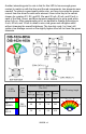
SBRGB PARTS LAYOUT DIAGRAM SBRGB • 17
TROUBLESHOOTING GUIDE If your Super Blinky does not work at all, re-check the following: • Correct orientation of U1, VR1, D1 (the LED), and battery hookup. • Correct polarity of the electrolytic capacitors. • Correct placement of D3. • Use an eye loupe to closely examine your parts placement for any pins that may have overlapped two pads, solder joints that could be open, or any large blobs of solder that maybe short across two or more pins. • Correct battery installation, and a good battery.
The Ramsey Kit Warranty Please read carefully BEFORE calling or writing in about your kit. Most problems can be solved without contacting the factory. Notice that this is not a "fine print" warranty. We want you to understand your rights and ours too! All Ramsey kits will work if assembled properly. The very fact that your kit includes this new manual is your assurance that a team of knowledgeable people have field-tested several "copies" of this kit straight from the Ramsey Inventory.
SUPER BLINKY SMT PRACTICE KIT Quick Reference Page Guide Introduction ...................................... 4 Circuit Description ............................ 5 Parts List .......................................... 9 Assembly Steps ............................... 10 Using the SBRGB ............................ 16 Schematic Diagram ......................... 17 Parts Layout Diagram ...................... 17 Troubleshooting Guide .................... 18 Specifications...................................