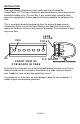
COMPUTEMP 255 BINARY THERMOMETER KIT Ramsey Electronics Model No. CT255 A really neat educational kit to learn the principles of binary math, how simple digital to analog converters work, and how instrumentation amplifiers may be used to measure the environment.
RAMSEY TRANSMITTER KITS • FM100B Professional FM Stereo Transmitter • FM25B Synthesized Stereo FM Transmitter • MR6 Model Rocket Tracking Transmitter • TV6 Television Transmitter RAMSEY RECEIVER KITS • FR1 FM Broadcast Receiver • AR1 Aircraft Band Receiver • SR1 Shortwave Receiver • SC1 Shortwave Converter RAMSEY HOBBY KITS • SG7 Personal Speed Radar • SS70A Speech Scrambler • BS1 “Bullshooter” Digital Voice Storage Unit • AVS10 Automatic Sequential Video Switcher • WCT20 Cable Wizard Cable Tracer • ECG1 He
Ramsey Publication No. MCT255 Price $5.00 KIT ASSEMBLY AND INSTRUCTION MANUAL FOR COMPUTEMP 255 BINARY THERMOMETER KIT TABLE OF CONTENTS Introduction ...................................... 4 Circuit Description ............................ 5 Schematic Diagram.......................... 13 Parts Layout Diagram ...................... 14 Parts List .......................................... 15 Assembly Instructions ...................... 17 Case Assembly ................................
INTRODUCTION Years ago Ramsey Electronics had a really neat little kit called the CompuTemp 127. This was a favorite kit purchased by many who were into the electronics hobby in the ‘70s and ‘80s. It was unfortunately retired to make space for a growing list of other popular kits being added to the catalog at the time.
CIRCUIT DESCRIPTION There’s a lot of circuitry in the CT255 that is in use to this day in a variety of circuits. We will begin with the temperature sensor itself, detailing how we did this 20 years ago and how we do it now. The actual temperature sensor is the LM35DZ. It is a specialized part that is pre-calibrated at the factory to output 10mV per degree Celsius. For example if we connected the part to power and measured the output at 0 degrees Celsius, the output would be 0mV.
The DAC (Digital to Analog Converter) The resistor values in this ladder are chosen to give us nice even steps in the voltage range we are able to work with. The outputs of the counter can’t actually achieve 5 volts with the LEDs on the output, but really close at 4.67V. We then figure what the voltage will be across R38 when all outputs of the counter are at 4.67V and we will have the maximum output of our DAC. In this case it is 3.10V. Of course the minimum works out to be 0V.
in series with the input to reduce any noise that may be present on the temperature sensor to increase accuracy of your reading. C3 in the feedback branch is also used to reduce noise in the reading. In the Celsius jumper setting, R37 and R27 are used to adjust the gain of our temperature sensor for a Celsius reading. The gain of a non-inverting amplifier is calculated by the formula : A = 1 + Rf / Ri. Where Rf if the feedback resistor R27, and Ri is the input resistor R37.
How the counter oscillator works U1:D is set up as a simple oscillator to generate our clock pulses that drive the ripple counter. When the comparator U1:B output is low, this circuit will run normally, generating pulses for our counter. When the U1:B comparator output is high, the oscillator stops. This is how the count is “held” for display. This oscillator works through the same principle as the comparator, by comparing the charge voltage across C1 charged through R1 to the voltage at pin 12.
to add 32. We do this by switching in R22 into the circuit, which combined with R23 adds in the 32 offset that we need. The problem however is this acts like a voltage divider on the output of U1:A our scaling amplifier, so now we have to adjust the non-inverting amplifier’s gain to compensate. First off we need to set the zero point of the sensor to a count of 32. This requires us to have a voltage on the opamp pin 6 of 12.16mV * 32 * 2.
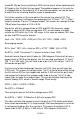
At 100.0 degrees Fahrenheit the temperature sensor will have an output of a value related to Celsius, so to make life easier, we will convert to Celsius first. So: C = 5/9(F-32) or C = 5/9(100—32) which is 37.78 degrees Celsius. This means the output of the sensor should be 377.8mV at 100.0 F. So to convert 377.8mV to 1.965 volts we need to multiply by: 1.965 / 0.3778 or 5.201. This will be the gain we need from the non-inverting amplifier.
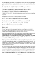
128 times to get the most significant LED to change state just once. Normally an 8 bit number has these significant values: Bit #: 7 6 5 4 3 2 1 0 Value: 128 64 32 16 8 4 2 1 Say bits 7, 3, and 0 are on, all others are off. The value would then be 128 + 8 + 1 or 137. Say instead bits 6, 5, 4 and 1 are on, all others are off. Our value would then be 64 + 32 + 16 + 2 or 114. Our display is set up to read from 0.0 degrees to 127.5 degrees in 1/2 degree steps.
You may notice though that the smallest step in this case is 1/256. This 8 bit DSP is unable to accurately represent this number smaller than 3.906E-3. Most fixed points DSPs however are 16 bit, 24 and 32 bits. 24 bits of resolution means the smallest number we can represent becomes 1/(2^24) which is 5.96E-8, which is considerably smaller and more accurate. Still the math isn’t perfect, and these “steps” will accumulate over time and cause errors. A 24 bit DSP number is usually in a 0.
CT255 SCHEMATIC DIAGRAM CT255 • 13
CT255 PARTS LAYOUT DIAGRAM CT255 • 14
PARTS SUPPLIED WITH YOUR CT255 KIT Capacitors 4 .1 µF disc capacitor (marked .
RAMSEY "LEARN-AS-YOU-BUILD KIT ASSEMBLY There are numerous solder connections on the CT255 printed circuit board. Therefore, PLEASE take us seriously when we say that good soldering is essential to the proper operation of your binary thermometer! • • • Use a 25-watt soldering pencil with a clean, sharp tip. Use only rosin-core solder intended for electronics use. Use bright lighting; a magnifying lamp or bench-style magnifier may be helpful. Do your work in stages, taking breaks to check your work.
CT255 THERMOMETER ASSEMBLY INSTRUCTIONS Although we know that you are anxious to complete the assembly of your binary thermometer kit, it is best to follow the numbered assembly steps when building. Try to avoid the urge to jump ahead installing components. Since you may appreciate some warm-up soldering practice as well as a chance to put some landmarks on the PC board, we’ll first install some of the larger components.
installed). Since a diode will only conduct when it is forward biased, this diode acts as a “reverse voltage” protection circuit. Diodes are often used as “one-way switches” in this manner to protect internal circuitry. 3. Identify C8, the 470 uF electrolytic capacitor (small cylindrical component coated with plastic and marked 470). Electrolytic capacitors are polarized with a (+) and (-) lead and must be installed in the correct orientation.
Next we will install some of the output voltage divider resistor networks. The circuit board has been laid out to avoid confusion with these multiple rows, and we will try to avoid sounding too redundant when installing them, Remember to save those leads as we will be installing some jumper wires very soon. Pay particular attention when installing so as not to mount the resistors in the improper locations. 7. Install R36, R33, R29, R26, R21, R19, and R17, all 10K ohm (brownblack-orange). 8.
16. Install C2, 10 uF electrolytic capacitor. Remember to observe polarity with electrolytic capacitors! Check the parts placement diagram for correct orientation. 17. Install R34, 10K ohm (brown-black-orange). 18. Install R30, 10K ohm (brown-black-orange). 19. Install R4, 10K ohm (brown-black-orange). 20. Install R2, 10K ohm (brown-black-orange). 21. Install C1, 1 uF electrolytic capacitor. Remember to observe correct polarity! 22. Install R1, 47K ohm (yellow-violet-orange). 23.
install all eight so that they are in line. A trick may be to fashion a cardboard “standoff “ and pre-bend the LEDs before installing 35. Install D1, one of the LEDs. The flat side is oriented as shown in the diagram. Leave it standing about 3/4 inch off of the board when soldering. After soldering bend it over to a 90º angle at its midpoint so that it faces the outside of the board. Observe the following diagrams for proper orientation.
40. FOR REMOTE SENSOR OPERATION. If you wish to run the sensor to a remote location, you will need to obtain a 3.5 mm stereo plug and wire as shown in the following figure. Flat Side LM35DZ RING 3.5 mm Stereo Plug (Not Included) TIP SHIELD Remember that the temperature sensing circuitry is relying on a very small voltage measurement to determine the temperature, so use a good quality shielded cable for remote sensing applications. 41.
CONGRATULATIONS ! Your binary thermometer is now complete! Have a final look over your work, paying particular attention to the orientation of diodes, capacitors, and IC’s. Remember that any problems you find now can save time and effort after the unit has been cased up and final assembled. ASSEMBLY INSTRUCTIONS FOR CUSTOM CASE The enclosure is a key element to the overall pride you will have upon completing your Ramsey kit.
USE OF YOUR COMPUTEMP 255 Now we are ready for the moment of truth, the initial power up and running of your binary thermometer. Energize the unit with a suitable 7.5 to 12DC power supply (noting that the center pin of the power supply is the positive connection) and watch your thermometer count up the first of many times. After a few seconds the display should reset and re-count to the current temperature.
TROUBLESHOOTING GUIDE If your CT255 does not work at all, recheck the following: • correct orientation of VR1, U1, and U2 (see PC board layout diagram) • You should be able to measure the voltage on the input and output terminals of voltage regulator VR1. The input should be whatever the supply voltage is specified at, while the output should be 5 VDC +/- 5%. • correct polarity of all electrolytic capacitors.
If all else fails, call or email Ramsey Tech Support at 585-924-4560 or tech@ramseyelectronics.com. We’ll try to help talk you through the problem. CONCLUSION We sincerely hope that you enjoy the use of this Ramsey product. As always, we have tried to compose our manual in the easiest, most user-friendly format that is possible. As our customers, we value your opinions, comments, and additions that you would like to see in future publications. Please submit comments or ideas to: Ramsey Electronics Inc.
The Ramsey Kit Warranty Please read carefully BEFORE calling or writing in about your kit. Most problems can be solved without contacting the factory. Notice that this is not a "fine print" warranty. We want you to understand your rights and ours too! All Ramsey kits will work if assembled properly. The very fact that your kit includes this new manual is your assurance that a team of knowledgeable people have field-tested several "copies" of this kit straight from the Ramsey Inventory.
CT255 BINARY THERMOMETER KIT Quick Reference Page Guide Introduction ...................................... 4 Circuit Description ............................ 5 Schematic Diagram.......................... 13 Parts Layout Diagram ...................... 14 Parts List .......................................... 15 Assembly Instructions ...................... 17 Troubleshooting Guide..................... 25 Warranty ..........................................