Electronic Dripping Faucet Ramsey Electronics Model No. EDF1 Who would’ve ever thought that you would want the sound of a dripping faucet in your house!! Especially after seeing how annoying it was on all those cartoons we used to watch! Add an unusual sound to your next alarm project with this unique noisemaker. • Unusual sound. • Adjustable volume and decay. • Runs on 4V to 9V DC. • Small size for easy mounting.
PARTIAL LIST OF AVAILABLE KITS: RAMSEY TRANSMITTER KITS • FM10A, FM25B FM Stereo Transmitters • AM1, AM25 Transmitter RAMSEY RECEIVER KITS • FR1 FM Broadcast Receiver • AR1 Aircraft Band Receiver • SR2 Shortwave Receiver • AA7 Active Antenna • SC1 Shortwave Converter RAMSEY HOBBY KITS • SG7 Personal Speed Radar • SS70A Speech Scrambler/ Descrambler • TT1 Telephone Recorder • SP1 Speakerphone • MD3 Microwave Motion Detector • PH14 Peak hold Meter • LC1 Inductance-Capacitance Meter RAMSEY AMATEUR RADIO KITS •
Ramsey Publication No. EDF1 Manual Price Only $5.00 KIT ASSEMBLY AND INSTRUCTION MANUAL FOR Electronic Dripping Faucet TABLE OF CONTENTS Introduction to the EDF1 ................................... 4 EDF1 Circuit Description................................... 4 “Learn-As-You-Build” Kit Assembly ................... 5 Parts List ........................................................... 6 Assembly Steps ................................................. 7 Setup and Testing ..................................
INTRODUCTION Have you ever had a project that you needed an alarm or alert signal for, but you were tired of the same old “beep beep”? Have you ever made an annoyance alarm to surprise that special someone, but the sound just wasn’t irritating enough? Well, help has arrived! The Ramsey EDF1 will provide you with a small, easy-to-mount noisemaking solution to fill all your unique auditory needs.
RAMSEY Learn-As-You-Build KIT ASSEMBLY There aren’t that many solder connections on the EDF1 printed circuit board, but you should still practice good soldering techniques. • • • • Use a 25-watt soldering pencil with a clean, sharp tip. Use only rosin-core solder intended for electronics use. Use bright lighting, a magnifying lamp or bench-style magnifier may be helpful. Do your work in stages, taking breaks to check your work.
EDF1 PARTS LIST Sort and “check off” the components in the boxes provided. We do our best to pack all our kits correctly but it is possible that a mistake has occurred and we missed a part. Please note that physical descriptions of parts are for those currently being shipped. Sometimes the parts in your kit may have a different appearance but still have the same values.
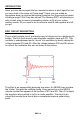
EDF1 PC BOARD ASSEMBLY STEPS Remember to save at least one clipped off component lead for use as a jumper later in the construction process. 1. Let’s start with U2, the NE555 timer. The NE555 repeatedly starts the oscillator that produces the dripping sound. Install it down at the bottom middle of the board.
17. Install R10, 2K ohm resistor, [red-black-red] under Q1. 18. Install R5, 10K ohm resistor [brown-black-orange], to the right of R10 19. Install C3, .01 uF ceramic disc capacitor [marked 103] next to R5. 20. Install R4, 47K ohm resistor [yellow-violet-orange], next to C3. 21. Install R1, 100K ohm resistor [brown-black-yellow], next to R4. 22. Install C2. .01 uF ceramic disc capacitor, under Q1. 23. Install D1, 1N4148 silicon diode, under C2.
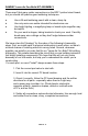
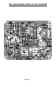
EDF1 MAIN BOARD PARTS LAYOUT DIAGRAM EDF1• 9
EDF1• 10
The Ramsey Kit Warranty Please read carefully BEFORE calling or writing in about your kit. Most problems can be solved without contacting the factory. Notice that this is not a "fine print" warranty. We want you to understand your rights and ours too! All Ramsey kits will work if assembled properly. The very fact that your kit includes this new manual is your assurance that a team of knowledgeable people have field-tested several "copies" of this kit straight from the Ramsey Inventory.
TABLE OF CONTENTS Introduction to the EDF1.................................... 4 EDF1 Circuit Description ................................... 4 Parts List............................................................ 6 Assembly Steps ..................................................7 Setup and Testing .............................................8 Troubleshooting Guide .......................................8 EDF1 Parts Layout Diagram ...............................9 EDF1 Schematic...........................