
Instruction manual


VLF1 • 14
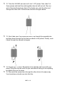
31. Install Q1 the 2N3904 NPN transistor next to C13. This provides
amplification for the mixed signal fed to the output jack. Be sure to align
the part with the outline on the board. The flat side should face the RCA
jacks at the bottom of the board.
32. Install R9, 270 ohm resistor (red-violet-brown) next to C3.
33. Install R8, 18 ohm resistor (brown-gray-black) next to Q1.
Now take a break from this part of the board and mosey over to the left side
and you can install the heart of the VLF1, the integrated circuits.
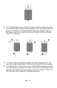
34. Solder in U2, the MC74HC04AN Hex Inverter. Be sure to observe the
direction when placing it. ICs soldered in the wrong way tend not to work.
Its outline on the board has a notch at one end. Line this up with the notch
on the top of the IC. The 7404 is part of the crystal oscillator that
generates the 4MHZ Clock.
35. Take a previously saved piece of clipped off lead and bend it into the
form of a staple that will fit in the holes marked “JMP2”. Place it into the
holes as though it’s a resistor or capacitor and solder it in place.
35. Install X1, the 4MHz crystal at the end of U2. It doesn’t matter which
way it goes in.
36. Install C8 and C9, 22pF capacitors (marked 22). These parts, along
with R4 and C10, set the oscillating frequency.
37. Install R4, 1M ohm resistor (brown-black-green).
38. Install C10, 40pf variable capacitor
39. Install U1, the CD74HC4053E analog multiplexer/demultiplexer, next
to U2. Again, be sure that the part is correctly oriented using the part
outline on the board. It Is lined up backwards from U2. U1 does the
switching that mixes the low frequency input with the 4MHz clock.
You’re in the home stretch!
40. Install C14, .1uF ceramic disk capacitor (marked 104), next to R8.
41. Install R7, 3.3K ohm resistor, next to C14.
42. Install C12, .1uF ceramic disk capacitor (marked 104).
43. Install D1, 4002 silicon diode.
44. Install L4, 100uH inductor (marked brown-black-brown).
45. Install C16, 10uF electrolytic capacitor, next to L4. Be sure to observe
polarity.
46. Install C15, 1000uF electrolytic capacitor, next to C16. Be sure to
observe polarity.