Ramsey Electronics Model No. STC1 Now you can give your home stereo transmitter all of the features found in a professional radio station! Control and prevent overmodulation, interference from high frequency signals such as TVs and older CD players, and “sweeten” the mix with Bass, Presence, and Brilliance.
RAMSEY TRANSMITTER KITS • FM10A, FM25B FM Stereo Transmitters • TV6 Television Transmitter • FM100B Super Pro FM Stereo Transmitter RAMSEY RECEIVER KITS • FR1 FM Broadcast Receiver • AR1 Aircraft Band Receiver • SR2 Short-wave Receiver • AA7 Active Antenna • SC1 Short-wave Converter RAMSEY HOBBY KITS • SP1 Speakerphone • MD3 Microwave Motion Detector • PH14,15,16 Peak hold Meters, great for VU meters! • LC1 Inductance-Capacitance Meter • TFM3 Tri-Field Meter • ECG1 Heart Monitor • LABC1 Lead Acid Battery C
Ramsey Publication No. STC1 Price $5.00 KIT ASSEMBLY AND INSTRUCTION MANUAL FOR STC1 STEREO TRANSMITTER COMPANION TABLE OF CONTENTS Introduction .....................................4 How Does It Work? .........................5 Learn As You Build .........................7 Parts List .........................................8 Construction..................................10 Schematic Diagram ......................14 Setup And Testing ........................21 Using The STC1 ...........................
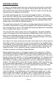
INTRODUCTION TO THE STEREO TRANSMITTER COMPANION Knowing how troublesome different audio sources can be when trying to transmit them over the air, we have come up with a product that will eliminate many of the problems. This kit allows the FM10A and the FM25 stereo transmitters to have the same quality audio and transmission that the professional radio stations have.
HOW DOES IT WORK? To help you understand where we are in the circuit you will want to look at the circuit diagram in the center of the manual. We will work from the input of the left channel to the output of the left channel. We don’t need to look at the right channel since it is identical to the left half. The audio signal coming into J1 is a line level signal at about 1 volt peak-topeak, which is a 0dB line level signal (standard). The audio level is cut in half by resistors R63 and R28.
When this voltage on pin 5 of U2:B goes higher than 5 volts of the supply on pin 6 of U2:B, the output of U2:B goes high, thus lighting the LED clip indicator. The other part of the signal goes to U3, a switched capacitor lowpass 8th order Butterworth filter. These filters are really neat since they don’t need any high accuracy frequency dependent parts, and don’t require pancakes. All that is needed is a good steady TTL clock signal to set the cutoff frequency.
RAMSEY “LEARN-AS-YOU-BUILD” ASSEMBLY STRATEGY Be sure to read through all of the steps, and check the boxes as you go to be sure you didn't miss any important steps. Although you may be in a hurry to see results, before you switch on the power check all wiring and capacitors for proper orientation. Also check the board for any possible solder shorts, and/or cold solder joints.
RAMSEY STC1 PARTS LIST Semiconductors ❒ 2 LF347 Quad Op-Amps (U1,2) ❒ 1 74HC74 Dual type ‘D’ flip-flops (U6) ❒ 2 MAX291 8th order Butterworth Switched Capacitor Filters (U3,5) ❒ 6 1N4148 small signal diodes (small glass body with black stripe) (D1,2,3,4,6,8) ❒ 1 4.9 to 5.
Capacitors ❒ 5 100pF ceramic capacitors (marked 100, or 101) (C1,9,18,27,45) ❒ 1 470pF ceramic capacitor (marked 470 or 471) (C46) ❒ 4 .001uF ceramic capacitors (marked .001, 102, or 1n) (C6,16,25,32) ❒ 4 .0047uF or .005uF ceramic capacitors (marked .0047, 472, .005, or 502) (C7,10,29,34) ❒ 2 .01uF ceramic capacitors (marked .01, 103, or 10n) (C38,42) ❒ 2 .022uF or .02uF ceramic capacitors (marked .022, 223, .02 or 203) (C8,C31) ❒ 2 .047uF or .05uF ceramic capacitors (marked .047, 473, .
CONSTRUCTION OF THE STEREO TRANSMITTER COMPANION Sort out all of your parts to begin with, making sure you have all of the parts required. You can use old egg cartons to hold various parts to make them easier to find. We will begin building the kit from the back end of the board where all the jacks will eventually be placed. Make sure to mount parts on the correct side! You will want to use the parts layout diagram to assist you in finding where the parts go.
diodes in the kit. Since the appearance of this part is likely to change as we order these parts in the factory, this is how we will need to identify them. Make sure the banded end of the diode is installed in the same direction as shown in the parts layout diagram. ❒ 10. Using a piece of scrap component lead from the parts you have installed earlier, install JMP3, a jumper. Jumpers act as “bridges” over other circuit paths on the PC board, allowing for a better routing of the board. ❒ 11.
❒ 28. Install R25, a 10K ohm resistor (brown-black-orange). ❒ 29. Install R26, a 10K ohm resistor (brown-black-orange). ❒ 30. Install R30, a 10K ohm resistor (brown-black-orange). ❒ 31. Install R7, another 10K ohm resistor (brown-black-orange). ❒ 32. Install R5, a 10K ohm resistor (brown-black-orange). OK, before we get ahead of ourselves here, we are going to go back to where we began and begin to install some of the larger components.
❒ 41. Install C6, a .001uF ceramic capacitor (Marked .001 or 102). ❒ 42. Install X1, the 6.00MHz crystal (Metal can marked 6.000). ❒ 43. Install Q1, the 2N3904 type small signal transistor. Observe the correct orientation of the flat side. You have just completed the 6MHz oscillator section of the PC board. This circuit is called a Colpitts oscillator, and is very good at producing the voltage levels and frequency we need to see at the inputs of U6, the CMOS type ‘D’ flipflop.
STC1• 14
STC1• 15
❒ 58. Install C31, a .022uF ceramic capacitor (marked .022 or 223). ❒ 59. Install R8, a 3.3K ohm resistor (orange-orange-red). ❒ 60. Install R11, a 1.8K ohm resistor (brown-gray-red). ❒ 61. Install R12, a 1.8K ohm resistor (brown-gray-red). ❒ 62. Install C10, a .0047uF or .005uF ceramic capacitor (marked 472, .0047, .005, or 502). ❒ 63. Install R37, a 1.8K ohm resistor (brown-gray-red).
❒ 73. Install C13, a 10uF electrolytic capacitor. Again note proper orientation. ❒ 74. Install R18, a 2.2K ohm resistor (red-red-red). ❒ 75. Install R23, one of the 100K ohm trimmer potentiometers (orange top marked 104). This trimmer allows us to adjust the output level of the STC1 where clipping begins. ❒ 76. Install U2, the other LM347 quad op-amp. Make sure all 14 pins are through the PC board before soldering it to the board.
❒ 95. Install R62, a 4.7M ohm resistor (yellow-violet-green). Guess what? we have just completed the limiter circuitry and the peak hold detectors that let us know when clipping occurs. Now we are on to complete the remainder of the kit, the 8th order switched capacitor filters. ❒ 96. Install R19, a 1K ohm resistor (brown-black-red). ❒ 97. Install R44, a 1K ohm resistor (brown-black-red). ❒ 98. Install R52, a 10K ohm resistor (brown-black-orange). ❒ 99. Install C43, a 10uF electrolytic.
❒ 117. Install C40, a 10uF electrolytic capacitor. Again check polarity. ❒ 118. Install R41, a 10K ohm resistor (brown-black-orange). Well, we are almost done with the assembly of our kit. Now all we have left to do is install some of the larger components to finish it off. We will begin at the back of the board... ❒ 119. Install J1, the Left IN RCA plug. Make sure to use plenty of solder to mount these RCA plugs.
Wow! we are finally finished installing parts into the board. You may of noticed that you have two LEDs left over. This is where you get to make a choice of how and where you want to mount these. If you have bought the case with this kit, follow the following directions so that the LEDs line up with the case front panel. Otherwise you can put them anywhere you want, just make sure that they are installed in the correct direction so they will light.
SETUP AND TESTING: You can test your STC1 by simply hooking it up and trying it or by using test equipment. For a test with testing equipment you will need: ❍ Audio Signal Generator ❍ DMM or oscilloscope ❍ 9 to 15 volt DC power supply. All we want to do here is verify that our assembly has been done correctly, and calibrate the unit for proper operation.
USING THE STC1: The STC1 is simply a sound processor. It is installed in series to process the audio right before it goes to the transmitter itself. No more processing should be done on the audio between the STC1 and the transmitter, otherwise it throws off the clipping settings. If you have an equalizer connected to your transmission setup, connect it before the STC1. An example setup is shown to give you an idea of a setup that we have here at Ramsey.
EXAMPLE HOOKUP STC1• 23
PARTS LAYOUT DIAGRAM STC1• 24
PARTS VALUE DIAGRAM STC1• 25
TROUBLESHOOTING TIPS PROBLEM: No 1.5MHz oscillator signal. SOLUTION: First check your testing procedures to make sure your scope is on the correct settings and that you have the power on the STC-1. If so, check the collector of Q1 for 6MHz. If you do not have signal there, check surrounding parts for shorts or cold solder joints. Otherwise, check U6 for power on it’s pins,. PROBLEM: One channel is out, the other works OK. SOLUTION: You may have a short or open somewhere through the circuit.
The Ramsey Kit Warranty Please read carefully BEFORE calling or writing in about your kit. Most problems can be solved without contacting the factory. Notice that this is not a "fine print" warranty. We want you to understand your rights and ours too! All Ramsey kits will work if assembled properly. The very fact that your kit includes this new manual is your assurance that a team of knowledgeable people have field-tested several "copies" of this kit straight from the Ramsey inventory.
STC1 Stereo Transmitter Companion Quick Reference Page Guide Introduction ..................................... 4 How Does It Work? ........................ 5 Learn As You Build ......................... 7 Parts List ........................................ 8 Construction ................................. 10 Schematic Diagram ...................... 14 Setup And Testing ........................ 21 Using The STC1 ........................... 22 Parts Layout Diagram ................... 24 Parts Value Diagram ..