
Instruction manual


STC1• 20
Wow! we are finally finished installing parts into the board. You may of noticed
that you have two LEDs left over. This is where you get to make a choice of
how and where you want to mount these. If you have bought the case with this
kit, follow the following directions so that the LEDs line up with the case front
panel. Otherwise you can put them anywhere you want, just make sure that
they are installed in the correct direction so they will light. LEDs are Light
Emitting Diodes, and like diodes, they only conduct in one direction. In the case
of an LED, they give off light as they conduct.
❒ a. Locate the supplied hook-up wire and cut it in half.
❒ b. Strip both ends of each wire back 1/4”.
❒ b. Solder one wire into the hole marked D7 for the left LED.
❒ c. Solder the other wire into the hole marked D9 for the right LED.
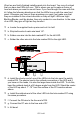
❒ d. Install the shorter end of one of the LEDs into the hole near the switch
marked D9. The shorter lead is the cathode connection of the LED and if
you have cut the leads, it is also the larger base inside the LED. To do this,
bend the cathode lead at a 90 degree angle from the LED. Stand the center
of the LED up about .7”-.75” from the surface of the PC board as shown
above.
❒ e. Install the cathode end of the other LED into the hole marked D7 using
the same procedure.
❒ f. Connect the D9 wire to the free end of D9.
❒ g. Connect the D7 wire to the free end of D7.
❒ h. All done!