2 METER FM 5 WATT TRANSMITTER KIT Ramsey Electronics Model No. FT146 Here's a simple hard-working transmitter that's ideal for repeaters, Fox-hunts, remote bases, Packet - you name it! Why tie up a whole transceiver to just use the transmitter? Fun and educational to build - you'll be on-the-air in an evening! • Direct, true FM for excellent voice and data quality. • Both Data and mike audio inputs • Solid 5 watt RF output - add our PA-146 for 40 watts • Crystal controlled with 146.
RAMSEY TRANSMITTER KITS • FM10, FM-25 FM Stereo Transmitters • TV6 Television Transmitter • Cube TV Transmitters RAMSEY RECEIVER KITS • FR1 FM Broadcast Receiver • AR1 Aircraft Band Receiver • SR2 Shortwave Receiver • AA7 Active Antenna • SC1 Shortwave Converter RAMSEY HOBBY KITS • RB1 Rat Blaster Rodent Repeller • SS70A Speech Scrambler • TT1 Telephone Recorder • WEB1 Walking Electronic Bug • MD3 Microwave Motion Detector • TFM3 Tri-Field Meter • ECG1 Heart Monitor RAMSEY AMATEUR RADIO KITS • DDF1 Doppler
Ramsey Publication No. MFT146 Price $5.00 KIT ASSEMBLY AND INSTRUCTION MANUAL FOR FT146 FM RECEIVER KIT TABLE OF CONTENTS Introduction to the FT146 .............. Circuit Description ......................... Parts List ........................................ FT146 Assembly Instructions ........ Testing and Alignment ................... Power Supply Considerations ....... Verifying RF Power Output............ Troubleshooting Guide .................. Enclosure Ideas .............................
INTRODUCTION Two meter FM has been around for years, but never with the popularity that is enjoyed today. In the old days, hams snooped around the local two-way radio shop in search of an obsolete taxi cab or police radio. These radios were in the 150 - 174 MHz business band and were easily moved down into the ham two meter band. On the chance that a UHF 450 - 470 MHz radio was found, it was modified for the ham 440 band.
and IC chip) give the equivalent of about 130 or more transistors and diodes. And, in addition to 13 inductors, a crystal and the various plus and jacks, there are over 60 capacitors and resistors. Surely, all that should result in a decent transmitter! You could easily spend twice the money plus hours of time trying to gather the equivalent parts from catalogs and still need to make your own circuit board.
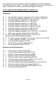
into transmit. There is no need to control the voltage to any other transistors since they all operate class "C". A class C amplifier draws no current unless it is driven, so there is no need to switch the later stages on and off. FT146 2 METER FM TRANSMITTER KIT PARTS LIST Capacitors: ❒ ❒ ❒ ❒ ❒ ❒ ❒ ❒ ❒ ❒ ❒ ❒ ❒ ❒ ❒ ❒ ❒ 1 2 or 2.2 pf disc capacitor (marked 2 or 2.2 or 2K or 2.2K) [C17] 1 4.7 or 5 pf disc capacitor (marked 4.7 or 5 or 4.
Inductors and ferrite cores: ❒ ❒ ❒ ❒ ❒ 2 2 2 2 2 Shielded can tunable inductor (marked 007007) [L9,13] Tunable inductor (pink plastic body) [L5,11] 6 hole ferrite bead core [L1,6] Small ferrite bead core [L10,12] Aluminum coil shield cans [for L5,11] Semiconductor devices: ❒ ❒ ❒ ❒ ❒ ❒ 1 2 1 1 2 1 ❒ ❒ ❒ ❒ ❒ ❒ 1 1 1 1 1 1 1N4002 style black epoxy diode [D5] 1N4148 style signal diode (glass body with black band) [D2,4] BB609 varactor diode (black body with yellow color band) [D1] Zener diode, 6.
RAMSEY Learn-As-You-Build KIT ASSEMBLY: There are over 200 solder connections on the FT146 printed circuit board. That means your work could be 99% perfect and you could STILL have 2 or 3 cold solder points or solder bridges. Since this circuit is more sophisticated than a direct-conversion HF receiver or a CW HF transmitter, a beginner or casual amateur could have a harder time tracing a problem due to a poor solder connection.
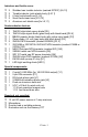
❒ 3. Install J2, the subminiature phone jack. Solder all three points. Be gentle and patient in inserting, so as not to damage the solder tabs. ❒ 4. Install R13, 5K trimmer pot. This is the modulation adjustment control. ❒ 5. Install U1, LM358 op-amp IC chip. In installing the IC, you may wish to use an 8-pin DIP socket rather than soldering the IC directly to the board. Reasons for doing this might include the peace of mind of being able to easily replace the IC if ever necessary.
❒ 21. Install R15, 10K ohm (brown-black-orange). ❒ 22. Install C33, .001 uf disc capacitor (marked .001, 1 nf or 102). ❒ 23. Install R16, 10K ohm, (brown-black-orange). Time for a breather and progress check.
❒ 41. Install R7, 470 ohm (yellow-violet-brown). ❒ 42. Identify Q1, a 2N3904 NPN transistor (marked 2N3904). Install Q1, observing correct placement of the flat side. ❒ 43. Install Q2, another 2N3904 NPN transistor (marked 2N3904).Observe correct placement of the flat side. ❒ 44. Install C27, 15 pf disc capacitor (marked 15 or 15K). ❒ 45. Install trimmer capacitor, C43 (black body with orange top). This trimmer is used for setting the FT146 exactly on frequency. ❒ 46. Install Y1, crystal.
❒ 60. Install C21, 4.7 or 5 pf disc capacitor (marked 4.7 or 5 or 4.7K or 5K). ❒ 61. Install L9, slug tuned shielded coil (marked 007007). This coil is part of the first tripler section. It is tuned to the third harmonic of the crystal oscillator. ❒ 62. Install L13, another slug tuned shielded coil (marked 007007). This coil is also part of the first tripler section. ❒ 63. Install TP1. Select a 1K resistor, R9 (brown-black-red). Trim back one lead wire to a length of inch.
stages of your transmitter. We recommend that you get them ready for installation before assembling the Driver and Final stages. If you prefer to proceed with those stages, winding coils as you go, that's fine, too, as long as you realize that all coil making details are provided in this section. The wire used for L1, 6, 10, and 12 is the smaller gauge enameled wire supplied with your kit. We give you plenty but if you mess up, you can get a whole 50' spool of it from Radio Shack (278-1341). ❒ 76.
FT146 • 14
FT146 • 15
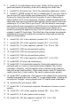
The "legs" or leads for inserting L2, L7, L3 and L4 should be about " long. These coils should sit about 1/8" maximum above the PC board when soldered. ❒ 80. Install L12, one of the small 3 turn ferrite bead RF chokes you wound. Pull it up snug against the PC board and solder. ❒ 81. Install TP2, another test point. Select a 1K resistor, R2 (brown-blackred). Trim back one lead wire to a length of inch. Bend this wire into a small loop as shown.
❒ 97. Install D4, 1N4148 style signal diode (glass body with black band). Observe correct orientation of the banded end. ❒ 98. Install TP3, the last test point. Select a 1K resistor, R29 (brown-blackred). Trim back one lead wire to a length of inch. Bend this wire into a small loop as before. Insert the resistor into the PC board and hold it carefully while you solder it to the board. ❒ 99. Install R22, 1K ohm (brown-black-red). ❒ 100. Install C15, 39 pf disc capacitor (marked 39 or 39K). ❒ 101.
❒ 112. Install C2, 100 to 220 uf electrolytic capacitor. Be sure to observe polarity - especially with this part since it is directly across the power supply and if reversed, could overheat so fast, so much that it could explode! ❒ 113. Install D5, 1N4002 style black epoxy diode, observe correct orientation of the banded end. ❒ 114. Install D2, 1N4148 style signal diode (glass body with black band). Observe correct orientation of the banded end. ❒ 115.
coil drastically whenever it is inserted into the coil. You may use a metal hex key if you are aware of this effect and are willing to remove the hex key from the coil after each adjustment. Although not recommended, with a little patience and sandpaper, a useable tool may be formed from a piece of wood or plastic rod. If you do make your own tool, be very careful to fully engage the slug because they are very brittle and any wedging or skewed turning will break it! ❒ 3.
❒ 8. Move your meter probe over to TP2, key the transmitter and adjust L5 and L11 for maximum negative reading. Once again, go back and forth between the two coils. You should get a reading of at least -120 mV. It is very important to tune for the best peak as this will ensure proper transmitter operation. ❒ 9. You should now be able to see RF power at the output antenna jack, J1. Adjust capacitor C12 for maximum RF power output. ❒ 10.
transmitter keying in a receiver is of some help, but even the simplest crystal oscillator can send a fine signal into your neighbor's receiver. Ideally, you have a small RF wattmeter, already inserted in the antenna line, capable of accurately measuring low output power in watts. And it cost you less than what you paid for the transmitter kit. Right? In the words of Wayne from "Wayne's World"... Not! So here are a few other ideas for you to try.
Amateur radio magazines and handbooks provide a variety of circuits for RF wattmeters and relative field-strength indicators, including methods of using your VOM as an indicating device. CQ magazine for March 1990 offers an article by KB4ZGC on how to make a highly accurate yet inexpensive dummy load and wattmeter capable of showing 1/10-watt differences in RF power.
"hum-m-m-, that's not a .001 uf where a 100 pf should be is it?" If there is a problem in getting the modulation working, a scope or audio amplifier will allow tracing down any problem in short order. The microphone audio is amplifier by about 350 times in U1:B. You should see at least a volt of audio at the output (pin 7) of U1:B. A low pass filter follows U1:B, you should still see at least a volt of audio at pin1 of U1. From there, the audio drives the varactor diode D1.
Here's a handy reference chart for the 5 pin DIN jack PIN # FUNCTION 1 +12 VDC power input 2 Power ground 3 Audio input 4 Audio ground 5 PTT (Push-To-Talk) Audio level required is in the 10 to 50 mV range. PTT requires a path to ground of less than 10K ohms. OTHER ENCLOSURE RECOMMENDATIONS Your finished transmitter can be installed in a variety of enclosures of your own design and choosing. You might be planning to combine several Ramsey circuit boards in a single enclosure.
NOTE ON REPLACEMENT PARTS: If you lose or damage parts during assembly or testing, you may, of course, order any needed replacement parts by writing or faxing the Ramsey Electronics, Inc. factory. Some of the more common parts may also be picked up at Radio Shack or other local parts distributors. Use EXACT values when replacing parts.
FT146 PARTS LAYOUT DIAGRAM FT146 • 26
The Ramsey Kit Warranty Please read carefully BEFORE calling or writing in about your kit. Most problems can be solved without contacting the factory. Notice that this is not a "fine print" warranty. We want you to understand your rights and ours too! All Ramsey kits will work if assembled properly. The very fact that your kit includes this new manual is your assurance that a team of knowledgeable people have field-tested several "copies" of this kit straight from the Ramsey Inventory.
FT146 2 Meter FM Transmitter Kit Quick Reference Page Guide Introduction to the FT146 .............. Circuit Description.......................... Parts List ........................................ FT146 Assembly Instructions ........ Testing and Alignment ................... Parts Layout Diagram .................... Ramsey Kit Warranty .....................