Sly Fox FOX-HUNT TRANSMITTER KIT Ramsey Electronics Model No. FHT-1 Get involved in the fox hunting fun! This kit combines a crystal locked true FM transmitter with a microprocessor for reliable operation. Multiple transmission “modes” assure a “sly fox” that will challenge any fox hunter. • Selectable high (5W) or low power (800 mW) operation - unit can even be programmed to change power levels during use! • Delay times from one minute to one hour ! • Stable crystal operation with a 146.
RAMSEY TRANSMITTER KITS • FM-10, FM-25 FM Stereo Transmitters • FM-1,2,4 FM Wireless Microphones • PB-1 Telephone Transmitter RAMSEY RECEIVER KITS • FR-1 FM Broadcast Receiver • AR-1 Aircraft Band Receiver • SR-1 Shortwave Receiver • AA-7 Active Antenna • SC-1 Shortwave Converter RAMSEY HOBBY KITS • SG-7 Personal Speed Radar • SS-70 Speech Scrambler • TT-1 Telephone Recorder • SP-1 Speakerphone • MD-3 Microwave Motion Detector • PH-10 Peak hold Meter • LC-1 Inductance-Capacitance Meter RAMSEY AMATEUR RADIO
Ramsey Publication No. FHT-1 Price $5.00 KIT ASSEMBLY AND INSTRUCTION MANUAL FOR SlyFox FOX HUNT TRANSMITTER KIT TABLE OF CONTENTS Introduction to the FHT-1 .............. 4 How it works .................................. 5 Parts list ........................................ 6 FHT-1 Assembly instructions ........ 8 Parts Layout diagram .................... 9 Schematic diagram ..................... 18 Initial testing ................................ 21 Programming ...............................
INTRODUCTION Finding a small, hidden radio transmitter may seem fairly easy at first, but with a sly transmitter the hunt can be made very challenging! With the interest in radio foxhunting on the rise, the need arose for a low cost transmitter to be used as the radio “fox” for the hunt! The problem is trying to configure a HT or converted commercial band transmitter to key at different times, ID itself, and perhaps leave a brief message.
FHT-1 CIRCUIT DESCRIPTION Basic overview: The FHT-1 is a crystal controlled FM transmitter that uses a varactor modulated crystal oscillator followed by a 9 times frequency multiplier and power amplifier. Test points are built-in for easy alignment. The “brains” of the unit is a Motorola microcontroller programmed to remember your CW ID and to control transmit power and timing.
FHT-1 FOX-HUNT TRANSMITTER KIT PARTS LIST Resistors and potentiometers: 1 2 ohm resistor (red-black-gold) [R6] 2 47 ohm resistors (yellow-violet-black) [R18,19] 1 51 ohm resistor (green-brown-black) [R10] 2 100 ohm resistor (brown-black-brown) [R28,40] 1 270 ohm resistor (red-violet-brown) [R8] 2 390 ohm resistors (orange-white-brown) [R33,34] 3 470 ohm resistors (yellow-violet-brown) [R7,16,20] 9 1K ohm resistors (brown-black-red) [R1,2,4,9,12,21,22,29,31] 1 2.
2 Small ferrite bead core [L10,12] 2 Aluminum coil shield cans [for L5,11] Semiconductor devices 1 1N4002 style black epoxy diode [D9] 3 1N4148 style signal diode (glass body with black band) [D2,4,5] 1 FS4059 varactor diode (black body with yellow color band) [D1] 1 Zener diode, 6.
RAMSEY Learn-As-You-Build KIT ASSEMBLY There are over 200 solder connections on the FHT-1 printed circuit board. That means your work could be 99% perfect and you could still have 2 or 3 cold solder points or solder bridges. Since this circuit is more sophisticated than a direct-conversion HF receiver or a CW HF transmitter, a beginner or casual amateur could have a harder time tracing a problem due to a poor solder connection.
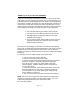
FHT-1 PC Board component placement diagram Shaded Parts used in Voice ID option S1 ExternalSwitch (opt) connections LED 1 LED 2 short leads TEST Connection s + Micro Battery Backup To Low Pass FilterBoard Ground Jumpers LongLead for mounting TP3 C7 FHT-1 • 9
1. Install J2, the subminiature phone jack.. Gently push the solder tabs through the PC board being careful not to bend or strain them. Solder all three tabs. 2. Install R41, 200 ohm trimmer pot (marked 201). This is the audio output or volume control. 3. Install R40, 100 ohm (brown-black-brown). This completes your earphone monitor output for the transmitter. 4. Install diode D9, the 1N4002 type (black body with a silver band).
black-orange). 17. Install R21, 1K ohm (brown-black-red). 18. Install C39, .01uF disc cap (marked .01 or 103 or 10nF). 19. Next we’ll install switch S2 (the run - program switch for the microprocessor). Gently slide the six solder pins through the PC board for connection. Solder all six connections. Use enough heat to “flow” the connections, especially on the ground “plane” connections. 20. Install C45, 10 uF electrolytic. Be sure to observe the correct polarity.
uses the same pin configuration as one. When installing be careful not to bend the solder pins, and make sure to push the switch flat to the board. 30. Install C41, 10 uF electrolytic. Watch that polarity! 31. Install R31, 1K ohm (brown-black-red). Notice that this is another “stand up” resistor. 32. Install C48, 150 pF disc capacitor (marked 150 or 151). 33. Install C40, .01 disc capacitor (marked .01 or 103 or 10nF). 34.
microcontroller, causing the crystal oscillator's frequency to change - in exact step with your CW ID. Voila, FM or Frequency Modulation! 44. Install C33, .01 uF disc (marked .01 or 103 or 10nF). 45. Install R8, 270 ohm (red-violet-brown). Make sure you stand this part up. 46. Install trimmer capacitor, C43 (black body with orange top). This trimmer is used for setting the FHT-1 exactly on frequency. 47. Install C27, 15 pf disc capacitor (marked 15 or 15K). 48.
60. Install C5, .01 uf disc capacitor (marked .01 or 10 nf or 103). 61. Install R3, 47K ohm (yellow-violet-orange). 62. Install C28, 39 pf disc capacitor (marked 39 or 39K). 63. Install Q3, 2SC2498 NPN Test point loop VHF transistor (marked C2498). Position the flat side as shown on Resistor the parts layout. Be advised that PC board this transistor has a different “pinout” than the 2N3904 that was previously installed so please trust us when we say to follow the parts layout diagram.
65. Install L13, another slug tuned shielded coil (marked 007007). This coil is also part of the first tripler section. 66. Install C21, 4.7 or 5 pf disc capacitor (marked 4.7 or 5 or 4.7K or 5K). 67. Install TP1. Select a 1K resistor, R9 (brown-black-red). Trim back one lead wire to a length of a quarter inch. Bend this wire into a small loop as shown. This loop will act as a convenient point to connect a test probe for tuning up your transmitter.
79. Install C25, 12 pf disc capacitor (marked 12 or 12K). 80. Install C17, 2 or 2.2 pf disc capacitor (marked 2 or 2.2). 81. Install another resistor test point, 1/4 in. TP2. Select a 1K resistor, R2 (brownblack-red). Trim back one lead wire to a L2,7 length of one quarter inch. Bend this wire into a small loop as shown. Insert the resistor into the PC board and hold it carefully while you solder it to the board.
84. Winding L2 and L7: Use the heavy gauge tinned bus wire in your kit for these coils. Wind these coils on the threads of the provided 5/16"X20 bolt to assure perfect forming of the coils. (You wondered what that big bolt was for - didn't you!) Both coils are 1½ turns. They appear to be 2 turns if viewed from the top. They will fit neatly into the PC board without any excessive bending or stretching. This is the front side and 2N5193 faces toward E C B JMP5 and R19. 85.
the side with the markings faces towards the jumpers that you just installed(JMP5 and JMP6). See the parts placement diagram for correct orientation. 100. Install R15, 2.2K (red-red-red). Notice that this part “stands up”. See the parts layout diagram for correct placement. 101. Install R16, 470 ohm (yellow-violet-brown). This part also “stands up”. 102. Identify and install the last 2N3904 transistor, Q7. Be sure to install with the flat side oriented correctly.
Also there is a provision to adjust the “high power” output. Notice that jumper J5 connects the collector of Q8 to the final transistor Q6. by removing this jumper and installing a suitable resistor (remember to calculate the power dissipation) the high power output can be lowered from its full 5 watt value.
case to the PC board ground plane. The SD1127 power transistor is designed by the manufacturer to be soldered directly to a PC board ground plane for heat sinking and proper VHF performance. This part is different from other metal can transistors in that the case is connected internally to the emitter rather than the collector. This provides much higher gain at VHF frequencies. 112. Install C19, 10 pf disc capacitor (marked 10 or 10K). 113. Install C6, 100 pf disc capacitor (marked 100 or 101).
#4-40 nuts Spacer nut #4-40 Screw 102 C7 SO-239 Female Ground Jumper Case Panel pass through the “component “ side of the circuit board. Pay particular attention to the disc capacitors to ensure that there is a good solder “flow” between the component lead and the PC traces. Be sure to lead enough lead exposed on the “solder” side to accomplish a good connection. 121. Install TP3, the last test point. Select a 1K resistor, R29 (brownblack-red), and install as before.
124. Install C15, 39 pf disc capacitor (marked 39 or 39K). 125. Install L4, 2½ turn coil wound previously. Make sure it seats as close as possible without touching the PC board. 126. Install C14, 56 pf disc capacitor (marked 56 or 56K). • • • • bridged over solder joints, misplaced components, transistors or diodes placed wrong, electrolytic capacitors installed wrong. 127. Install L3, another 2½ turn coil. Be sure it sits flush against the PC board. 128.
this is accomplished, proceed to slide the screws through the holes in the filter PC board, and finish up by installing the last two #4-40 nuts. 133. Now position the filter circuit board assembly at a right angle to the main circuit board. Carefully solder the two ground connections and capacitor C7 from the filter circuit board to the main board. Follow the diagram below for PC board placement. 134. Now solder the center pin of the SO239 connector to the filter circuit board assembly. 135.
CONGRATULATIONS This completes our assembly of the FHT-1 Sly Fox transmitter, now's a good time to give your masterpiece a good going over, being especially alert for any: TESTING, ALIGNMENT AND ADJUSTMENT To prepare your FHT-1 for testing, you'll need the following items: 1. The hexagonal, non-metallic alignment tool included with your kit. 2. A suitable 50 ohm dummy load. 3. Proper cable to connect from FHT-1 transmitter (SO239) to dummy load. 4. A 12 volt DC power source of at least 1 amp. 5.
7. Adjust L9 and L13 for maximum indication on TP1. No more than a turn or two is needed. You will have to go back and forth between these coils as they interact. You should get a reading of at least 50 mV. 8. Move your meter probe over to TP2 and adjust L5 and L11 for maximum negative reading. Once again, go back and forth between the two coils. You should get a reading of at least -90 mV. It is very important to tune for the best peak as this will ensure proper transmitter operation. 9.
VERIFYING TRANSMITTER RF OUTPUT The most important thing to know is whether your transmitter is delivering some measurable and reassuring level of RF power to the antenna. The sound of the transmitter keying in a receiver is of some help, but even the simplest crystal oscillator can send a fine signal into your neighbor's receiver. Ideally, you have a small RF wattmeter, already inserted in the antenna line, capable of accurately measuring low output power in watts.
at full brilliance presents only an 8.2 ohm load to the transmitter. Because of this, the transmitter may act "flaky" when tuning up into a light bulb, and by all means you should not consider a light bulb an accurate indicator of the FHT-1's performance! If ANY flashlight bulb lights up when connected to the antenna jack of this transmitter, you can be satisfied that you have RF output power at least equal to the DC power rating of the bulb you are using.
Amateur radio magazines and handbooks provide a variety of circuits for RF wattmeters and relative field-strength indicators, including methods of using your VOM as an indicating device. CQ magazine for March 1990 offers an article by KB4ZGC on how to make a highly accurate yet inexpensive dummy load and wattmeter capable of showing 1/10-watt differences in RF power.
cells" in series with your power source, if a full 13.6-15 volts DC is not Ramsey FHT-1 Processor Flow Chart available.
poor regulation, AC ripple content and RFI susceptibility. If your supply voltage is in the 11-12 volt range, you can expect a 600 to 800 ma current flow and about 4 watts of the RF output power. With a solid 13 to 14 volt supply, you can expect about 1 amp current draw and up to 5 or 6 watts of RF output power.
MODE 0 PROGRAMMING: The FHT-1 has 16 different modes of operation of increasing difficulty. The mode is selected by setting the DIP switch S3. By setting the mode you control; how long the transmitter is on the air, if a tone is present, power level, and the time until the next transmission. Mode 0 is the user programmable mode. You must program this mode first to enter your ID. 1. Turn off the FHT-1. 2. Connect a small monitor earphone to J2. 3. Center the earphone adjustment pot, R41, to mid-range.
All switches on equals the highest tone frequency. For a frequency of 1000 Hz set S3-4 and S3-1 on. 13. Close either the dot or dash paddle to enter the tone frequency. LED 2 and LED 1 will both go out. 14. Set the DIP switch for the desired operating mode. Mode 0 is the user programmable mode. Or you may select any other mode. 15. Switch S2 to RUN.
As you can see mode 1 will Ramsey send the IDKit (15sec.) then wait 45sec. and The Warranty then start over. This is the beacon mode Identifying once per minute. Please carefully BEFORE callingaor writing about Mostbe problems Mode read 2 Identifies then sends tone forin45 sec.your sokit. it will on thecan air be solved without contacting the factory. continuously. These modes will make the Fox easy to find for beginners.
Fox Hunt Transmitter FHT-1 Quick Reference Page Guide Introduction to the FHT-1 .............. 4 How it works ................................. 5 Parts list ........................................ 6 FHT-1 Assembly instructions ........ 8 Parts Layout diagram .................... 9 Schematic diagram ..................... 18 Initial testing ................................ 21 Programming ............................... 24 Troubleshooting ........................... 28 Ramsey kit warranty ...................