
Instruction manual


FHT-1 • 16
79. Install C25, 12 pf disc capacitor
(marked 12 or 12K).
80. Install C17, 2 or 2.2 pf disc capacitor
(marked 2 or 2.2).
81. Install another resistor test point,
TP2. Select a 1K resistor, R2 (brown-
black-red). Trim back one lead wire to a
length of one quarter inch. Bend this
wire into a small loop as shown. Insert
the resistor into the PC board and hold it
carefully while you solder it to the board.
Nine parts need handmade preparation
before installation in the transmitter RF
stages of your transmitter. We recommend
that you get them ready for installation before
assembling the Driver and Final stages. If
you prefer to proceed with those stages,
winding coils as you go, that's fine too, as
long as you realize that all coil making details are provided
in this section. The wire used for L1, 6, 10, and 12 is the
smaller gauge enameled wire supplied with your kit. We give you plenty but if
you mess up, you can get a whole 50' spool of it from Radio Shack (278-
1341).
82. Winding L1 and L6 RF chokes (two identical units ): Examine the
two cylindrical ferrite cores provided in the kit. Notice that there are six
holes at either end of these cylinder shaped units, arranged in two
groups of three. Cut 6" of enameled wire and following the drawing,
thread the wire, pulling each turn gently tight. Tin each end with solder
by holding your soldering iron and solder on the wire ends until the
enamel insulation melts away and the copper wire underneath coats
nicely with solder. Tin all the way up to the ferrite core body. Your
finished RF chokes should look like the diagram. Do not install either
part yet.
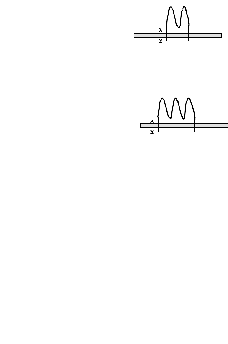
83. Winding L10 and L12: Locate the two small black ferrite beads
provided in the kit. Cut 2" of enameled wire and following the drawing,
thread 3 turns through the bead hole, pulling each turn "gently tight." Tin
each end with solder. Tin all the way up to the ferrite core body. Your
finished bead chokes should look like the diagram. Do not install either
part yet.
1/4 in.
1/4 in.
L2,7
L 3,4