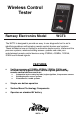
Wireless Control Tester Ramsey Electronics Model WCT3 The WCT3 is designed to provide an easy to use diagnostic tool to aid in identifying problems with wireless remote control devices and systems. These include but are not limited to automotive keyless entry, starter and tire pressure systems, wireless building access systems and even your entertainment remote control devices using 315MHz, 433MHz, 125KHz, 20KHz and Infrared signals.
PARTIAL LIST OF AVAILABLE KITS: RAMSEY TRANSMITTER KITS FM10A, FM25B, FM30, FM Stereo Transmitters FM100B, FM35 Professional FM Stereo Transmitters AM1, AM25 AM Broadcast Band Transmitters RAMSEY RECEIVER KITS FR1 FM Broadcast Receiver AR1 Aircraft Band Receiver SR2 Shortwave Receiver SC1 Shortwave Converter RAMSEY HOBBY KITS LBC6K Laser Beam Communicator SG7 Personal Speed Radar SS70C Speech Scrambler/Descrambler TT1 Telephone Recorder LLS1 Laser Light Show MD3 Microwave Motion
Ramsey Publication No. WCT3: Manual Price Only $5.00 INSTRUCTION MANUAL AND ASSEMBLY STEPS FOR WCT3 Wireless Control Tester TABLE OF CONTENTS Introduction ** ...................................... 4 Theory of Operation ............................. 5 Parts List ............................................ 10 Parts Layout Diagram ........................ 11 “Learn as you Build” ** ....................... 12 Assembly Steps ................................. 14 Schematic Diagram............................
INTRODUCTION The WCT3 can be used to detect 315MHz, 433MHz, 125KHz, 20KHz and Infrared signals generated by various devices such as, but not limited to, automotive key fobs, tire pressure sensors, building access control systems, and infrared remote control devices. The WCT3 provides verification of the presence of the various types of signals. It does not provide any information about the actual data transmitted by the device.
THEORY OF OPERATION The WCT3 consists of 4 separate stages, one for each of the wireless control signals to be detected. The sections are basically identical in operation but each is specifically designed to detect the signal of interest. In order to keep things simple we will describe the basic operation of one section and then briefly describe the differences between the sections.
amplifier stage formed by U1B and the resistors R5, R6, R8 and capacitor C7. U1B is a high gain, high frequency, high input resistance, low noise amplifier. There are 4 of these amplifiers in the U1 package and one is used for each of the 4 sections of the WCT3. The reason an amplifier with the characteristics of U1 is needed is because the detected signal level is extremely small, actually in the micro volt, (that’s 0.000001 volts), range.
is a spiral circuit trace near the ANT1 connection on the left side of the board. You will also notice that the detector diodes D3 and D4 are a different type. This is because of the much higher frequency we are working with. The diode package used on the other sections will not function at these frequencies. The Infrared section of the WCT3 is the least critical section even though the infrared signal is near the frequency range of visible light.
“+4.5V” voltage is referenced to the signal ground and not the power ground. If a reading is taken between the power ground and signal ground with reference to the signal ground you will see a reading of “-4.5V”. So the difference between the “+4.5V” and “-4.5V”, (measurements referenced to signal ground), points of the circuit is now +9 volts with reference to the power ground.
can move your hand REALLY, REALLY, REALLY …. fast. (If you can move that fast there are probably some military research facilities that would like to talk to you). For the same reason, if the light source is moved rapidly past the WCT3 you may also see the indicator flash indicating detection of the light. You are actually modulating the IR signal seen by the WCT3 by blocking and unblocking or moving the light source, (OOK modulation).
WCT3 PARTS LIST Each type and value of a surface mount component, (indicated by “[smt]”), is placed in its own labeled baggie. Be aware not all [smt] components have value markings so be careful not to mix them up. In the parts list an “X” in the reference designation indicates that an extra component or two is provided because they like to “fly away” due to the small size.
1 9V battery snap clip with red and black wires 1 Antenna bundle assembly (Pre-Assembled.
RAMSEY “LEARN-AS-YOU-BUILD” ASSEMBLY STRATEGY Completely read through all of the steps and check the boxes as you go to be sure you didn't miss any important assembly instructions. Although you may be in a hurry to see results, before you switch on the power check all wiring diodes, transistors, IC’s, and capacitors for proper orientation. Also check the board for any possible solder shorts and/or cold solder joints.
circuit board pad simultaneously. Apply a little more solder to the component lead and the pad when they are hot enough to melt the solder and remove the iron. DO NOT move the component lead or board until the solder cools a little. The finished joint should look like a drop of water on paper, clean, shiny, with joint completely filled. 8. Clip remaining component leads as close to the board as possible. For Surface Mount Technology (SMT) Components, the word "Install" means: 1.
ASSEMBLY STEPS Surface Mount Semiconductor Installation 1. Orient the board as shown in the board layout diagram on page 1 2. Install U1, the LF347 IC( marked LF347). Notice that there is an indented dot near one corner of the IC. This indicates the location pin 1 and the IC must be installed so this dot is to the upper left near the small white dot printed on the circuit board. Place the IC on the board and make sure all the leads on both sides of the IC align with all the solder pads on the board.
Resistor Installation: Let’s start with the four(4) 560 ohm resistors, marked 561. 9. Install R18, 560 ohm resistor 10. Install R19, 560 ohm resistor 11. Install R20, 560 ohm resistor 12. Install R32, 560 ohm resistor Now located the ten(10) 1K ohm resistors, marked 102. 13. Install R4, 1K ohm resistor 14. Install R7, 1K ohm resistor 15. Install R8, 1K ohm resistor 16. Install R9, 1K ohm resistor 17. Install R10, 1K ohm resistor 18. Install R11, 1K ohm resistor 19.
31. Install R27, 10K ohm resistor Almost there… let’s do the 150K ohm resistor, marked 154. 32. Install R31, 150K ohm resistor Locate the two(2) 330K ohm resistors marked 334. 33. Install R3, 330K ohm resistor 34. Install R6, 330K ohm resistor Locate the last resistors, six(6) 3.9M ohm resistors, marked 395, (that’s 3million, 900 thousand ohms.. 3,900,000 ohms). Three(3) of these resistors will be installed now and the 4th will be installed in a little while. Don’t lose it!!!! 35. Install R2, 3.
47. Install C9, .01uF capacitor 48. Install C10, .01uF capacitor 49. Install C14, .01uF capacitor 50. Install C15, .01uF capacitor 51. Install C16, .01uF capacitor 52. Install C17, .01uF capacitor Remember that 3.9M ohm resistor, marked 395, we didn’t install? Well, it’s R33 and now is the time to install it. 53 R33 is installed a little differently. We’re going to install it right on top of C2 that you installed in step 40.
Thru hole component installation: The remainder of the components are thru hole components. When installing all except the LED’s they should be inserted and placed as close to the circuit board as possible. 57. Next install D3 and D4, marked CDSH270. Notice that there is a black band on one end of the diodes. Place the diodes so band matches the wide white printed line on the board. Again place the body of the diodes against the circuit board.
61. Install D1, a RED LED 62. Install D6, a RED LED 63. Install D7, a GREEN LED 64. Install D10, a GREEN LED 65. Install D8, a Yellow LED 66. Install S1 push button switch Make sure to seat the body flush to the circuit board. Locate the 9 volt battery snap clip. This is the black connector with a red and black wire attached. 67. Trim the leads of the battery clip so they are 2.25 (two and a quarter, 2 1/4), inches long measured from the black cover. 68.
ANTENNA PLACEMENT Figure 2 TR3 TR1 TR2 S1 WCT3 22
FINAL ASSEMBLY You’re on the final leg of your journey. Now we’ll do some final mechanical assembly and testing and you’ll be using your WCT3 in no time. Locate the back of the case assembly. This is the part with a slide off door for the battery. Slide the battery cover off the case bottom and position the back so the inside is up and the battery compartment area is nearest you. 76.
the operation. Refer to “Theory of Operation”, on page 5, or “Troubleshooting”, on page 28, sections of this manual for further information. Final Case Assembly 82. Disconnect the battery and locate the top of the case. Place it over the case bottom with the circuit board in place and make sure all the LED’s and S1 are properly aligned with the holes in the top and that they are either flush or slightly recessed below the top surface. Switch S1 may extend slightly past the top.
Using the WCT3: 1. Press and hold the “Press To Test” button on the WCT3. The “Test Active” indicator will illuminate and any or all of the “315MHz”, “125KHz”, 20KIHz and “IR” indicators may flash momentarily. 2. With the WCT3 activated and in close proximity to the device being tested, activate the device being tested.
315MHz signal test: While holding the remote control in close proximity to the WCT3, activate the WCT3 and then the device under test. Results: WCT3 indicates 315MHz signal. Problem? If no signal indication is obtained there is a problem with the device such as a dead battery or other electronic problem.
Building access system signal test: This test assumes the access control system produces a constant 125KHz signal. Activate the WCT3 while holding it near the building access device reader. Results: The “125KHz” indicator on the WCT3 is illuminated. Problem? If no signal indication is obtained there is a problem with the building access system. Troubleshooting OK, so you have completed the assembly of your WCT3 and there’s something not quite right about it.
FINDING THE PROBLEM: You will need to have a multimeter available to proceed with the following procedures. Pushbutton S1 MUST be pressed in order to make voltage measurements. If a resistance measurement is indicated be sure to remove the battery before making the reading to avoid damage to your meter. You may need to refer to the schematic and board layout to determine the exact location of the test points. Readings will be indicated in the brackets, “[xxx]” , in the text below.
PROBLEM: D1 lights but I don’t get any indications from one or more of the sections Measure the voltage / resistance at the following points. “+” connection of the battery , [+8.5V to +9.1V]. Connection between R22 and R23 , [+4.5V to +5.2V]. U1 & U2 pin 4, [+8.5V to +9.1V] U1 & U2 pin 11, [0VDC] With out pressing pushbutton S1 measure the resistance at U1 & U2 pin 11, [0 ohms]. With out pressing pushbutton S1 measure the resistance at U1 & U2 pin 4, [1.7K ohms].
If you see a very small change and it does not go over the 1300mV it may be that the signal is not strong enough or there is a problem with the detector or amplifier. First, try to increase the signal level by repositioning the devices. The level you see will be proportional to the input signal strength. Unfortunately the level from the detector presented on U1 pin 3 may be so low the multimeter may not be able to measure it. You may need more sensitive equipment.
USER NOTES: WCT3 31
HOW TO RETURN YOUR WCT3 FOR SERVICE OR CONTACT US FOR MORE HELP If you are still unable to solve your kit problems you may send your kit in for repair. For instructions on how to return kits for repair please see the “Factory Repair of Assembled Kits” section of our Ramsey Kit Warranty page on the next page of this manual. Remember that we also have repair/replacement parts available for all our products. Just contact our sales department at the phone number below to order parts.
THE RAMSEY KIT WARRANTY 1. GENERAL: Notice that this is not a "fine print" warranty. We want you to understand your rights and ours too! All Ramsey kits will work if assembled properly. The very fact that your kit includes this new manual is your assurance that prior to release of this kit, a varied group of knowledgeable people have assembled this kit from scratch using this manual.
TABLE OF CONTENTS Introduction .......................................... 5 Theory of Operation ............................ 4 Parts List............................................ 10 Parts Layout Diagram ........................ 11 “Learn as you Build” .......................... 12 Assembly Steps ................................. 14 Schematic Diagram ........................... 18 Troubleshooting ................................. 27 How To Get Help From Ramsey ....... 32 Warranty .........................