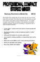
Ramsey Electronics Model No. MX10 Now here’s the simple easy to use mixer for all of you home brew DJs out there! This mixer has all of the features you will ever need to mix audio as the professionals do - in a small compact size! Perfect for DJing on the desktop transmitter, making car tapes, mixing for a wedding or anywhere else a mixer could be needed.
RAMSEY TRANSMITTER KITS • FM10A, FM25B FM Stereo Transmitters • AM1, AM25 AM Transmitters • TV6 Television Transmitter RAMSEY RECEIVER KITS • FR1 FM Broadcast Receiver • AR1 Aircraft Band Receiver • SR2 Short-wave Receiver • AA7 Active Antenna • SC1 Short-wave Converter RAMSEY HOBBY KITS • SP-1 Speakerphone • AVS10 Automatic Sequential Video Switcher • WCT20 Cable Wizard Cable Tracer • LABC1 Lead Acid Battery Charger • ECG1 Heart Monitor • BS1 “Bullshooter” Digital Voice Storage Unit • AVS10 Automatic Seque
Ramsey Publication No. MMX10 Price $5.00 KIT ASSEMBLY AND INSTRUCTION MANUAL FOR MX10 STEREO THREE INPUT MIXER Table of Contents Introduction ....................................4 Circuit Description ...........................5 MX10 Parts List ............................10 Assembly Procedure .....................11 Schematic Diagram ......................16 Initial Testing .................................23 Troubleshooting ............................24 Layout Diagrams.................
INTRODUCTION TO THE MX10 Seeing the need for a high fidelity low noise mixer to be used with our micropower transmitters, we came up with this easy to build compact mixer. The small size lends to the small size of the transmitter for portability.
MX10 CIRCUIT DESCRIPTION We will use the schematic diagram to step through the circuit and find out what makes it “tick”. There are plenty of different devices performing different tasks in the MX10. The most common active component is the opamps. These are used in a number of ways in the MX10, one of which is mixing. To perform mixing, an opamp is set up in what is called a summing amplifier. This amplifier does exactly what it says. It takes all of its inputs and adds them together on the output.
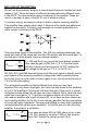
The next stage of the microphone amplifier has two diodes in the feedback loop. What are these for? you may ask. Well they are called clipping diodes. Diodes have a property of needing about .7 volts across them if the forward bias direction before they turn on. On signals under .7V P/P, the gain of the second stage is determined by Ri of 10K (R28) and Rf of 10K (R27). This gives us a gain of 1. But if our signal becomes greater than .7V P/P, then the diodes D1 and D2 begin to turn on.
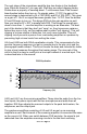
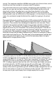
circuits. The earphone amplifiers LM386s have quite a bit of kick to them, which should be more than enough to out power most DJ systems. The peak hold meters serve the function of displaying peak amplitudes in your audio so your eye can see them. Normally a short duration pulse such as a drum beat or strum of a guitar has a very short time duration for the initial higher power sound.
RAMSEY “LEARN-AS-YOU-BUILD” ASSEMBLY STRATEGY Be sure to read through all of the steps, and check the boxes as you go to be sure you didn't miss any important steps. Although you may be in a hurry to see results, before you switch on the power check all wiring and capacitors for proper orientation. Also check the board for any possible solder shorts, and/or cold solder joints.
As with all Ramsey kits, we want to mount the parts AS LOW AS POSSIBLE to the board. A 1/4” lead length on a resistor not mounted close to the board can act as an inductor or an antenna, causing all sorts of problems in your circuit. Be aware though that if there are stand up components in your circuit, they don’t need to be squished to the board. Keep the portion of the resistor closest to the board mounted right on the board. For each part, our word "Install" always means these steps: ❒ ❒ ❒ ❒ 1.
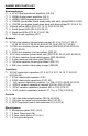
RAMSEY MX10 PARTS LIST Semiconductors ❒ 3 LF347 Dual operational amplifiers (U4,5,6) ❒ 2 LM386 Audio power amplifiers (U2,3) ❒ 2 LM3915 LED bargraph drivers (U7,8) ❒ 4 1N4002 type diodes (black epoxy body with white stripe)(D29,31,34,35) ❒ 6 1N4148 type diodes (small glass body with black stripe)(D1,2,5,6,8,19) ❒ 10 Small yellow LEDs (D3,10,11,12,13,14,22,23,24,25) ❒ 6 Small green LEDs (D4,7,9,18,20,21) ❒ 6 Small red LEDs (D15,16,17,26,27,28) ❒ 1 7808 +8 volt regulator (VR1) Resistors ❒ 30 10K ohm resistors
ASSEMBLY OF THE MX10 Now we are getting to the good stuff-assembling the MX10. We will begin by mounting first the low parts, beginning with the parts on the side of the board labeled as “PARTS” side on the PC board. When we are finished with that side, we will begin to install parts on the “CONTROL” side of the board. This side is where all of the controls go, and will be the side of the board facing the top of the case. In the case of this project we will attempt to go from top to bottom, left to right.
❒ 18. Install R27, a 10K ohm resistor (brown-black-orange). ❒ 19. Install R28, a 10K ohm resistor (brown-black-orange). ❒ 20. Install D1, a 1N4148 type diode (orange body with black stripe). Make sure that the cathode end (with the stripe) is installed in the same orientation as where the “arrow” is pointing to the stripe of the diode symbol. The stripe of the diode is the same as the stripe on the layout. ❒ 21. Use the same procedure to install D2, another 1N4148 type diode.
ready to continue with the rest of the project. ❒ 39. Install R54, a 10K ohm resistor (brown-black-orange). ❒ 40. Install R52, a 10K ohm resistor (brown-black-orange). ❒ 41. Install R82, a 10K ohm resistor (brown-black-orange). ❒ 42. Install R70, a 100K ohm resistor (brown-black-yellow). ❒ 43. Install D6, a 1N4148 type diode. This diode and U4:A form the “real diode” section of the peak hold circuit. “real diode” means that there is no .
❒ 59. Install R89, a 68K ohm resistor (blue-gray-orange). ❒ 60. Install R43, a 100K ohm resistor (brown-black-yellow). ❒ 61. Install R67, a 180 ohm resistor (brown-gray-brown). ❒ 62. Install R76, a 10K ohm resistor (brown-black-orange). ❒ 63. Install R77, another 10K ohm resistor (brown-black-orange). ❒ 64. Install R51, a 10K ohm resistor (brown-black-orange). ❒ 65. Install R49, a 10K ohm resistor (brown-black-orange). ❒ 66. Install R68, a 2.0 ohm resistor (red-black-gold). ❒ 67.
parts, we will quit going from left to right, top to bottom and begin to install parts close to one another. ❒ 81. Install C1, a 10uF electrolytic capacitor. Notice this is the first capacitor of this type. You want to pay close attention to the polarity markings on this part. In most cases the negative (-) side is marked on the capacitor, while the positive side (+) is marked on the parts layout.
MX10 Page 16
MX10 Page 17
❒ 101. Wow, it’s hard to believe we have come 100 steps already! Install C36, a 10uF electrolytic capacitor. Again check the orientation before continuing. ❒ 102. Install C34, a .1uF ceramic capacitor (marked .1 or 104). ❒ 103. Install C8, a .01uF ceramic capacitor (marked 103, 10n or .01). ❒ 104. Install C33, a 220uF electrolytic capacitor (orientation!) ❒ 105. Install C5, a .01uF ceramic capacitor (marked .01, 103 or 10n). ❒ 106. Install C6, a 10uF electrolytic capacitor. Orientation! ❒ 107.
❒ 125. Install J6, a 3.5mm mono microphone jack. (Identified by only three mounting pins instead of five) Note that they don’t fit exactly in the holes since a better jack was ordered that the one the kit was originally designed for. ❒ 126. Install J5, a 3.5mm mono microphone jack. We have just completed this entire side of the PC board and now we are ready to begin working on the other side of the board. Flip the board over and notice where all of the controls are to go.
and S4. ❒ 133. Install the next two yellow LEDs (D11 and D23) Check the long lead side! ❒ 134. Install two more yellow LEDs (D13 and D24). Again check the long lead side. ❒ 135. Install the last of the yellow LEDs to go in the meter (D14 and D25). There should be two left over for the microphone indicators. ❒ 136. Install the first of the red LEDs to go in the meter just to the right of the yellow LEDs (D15 and D26). Make sure the long leads are oriented correctly. ❒ 137.
❒ 146. Install R6, the last of the 10K ohm board mount pots. ❒ 147. Install R26, a 10K ohm slider potentiometer. Notice how the pot only installs easily one direction. Make sure that the leads under this slider and all others are trimmed short enough as to not short circuit to the body of the slider pots. Check to make sure all pins are through the board and that the part is flush before soldering. ❒ 148. Install R58, a 10K ohm slider potentiometer.
MX10 Page 22
INITIAL TESTING THE MX10 For this portion of the kit building experience you will need the following items: ❍ Line level source such as a tape deck, signal generator (SG-550) or CD player. ❍ Record level source such as a record player or signal generator. (Ramsey SG-550) ❍ A destination such as an audio amp, transmitter or earphones ❍ A microphone if you are planning on using one. ❍ 2 or more 3/8” stereo jacks to a pair of RCA jacks like the ones used with portable CD players.
TROUBLESHOOTING GUIDE Well, we sincerely hope you get to skip this portion of the manual, but this is here to help in the event of an emergency. Remember the detrimental effects an incorrectly installed component may have on your circuit. Keep this in mind as you troubleshoot your circuit for possible assembly errors. PROBLEM: Nothing at all on the output of the mixer. SOLUTION: Check your power supply voltages to make sure you have at least 12 volts between the tab of VR1 and pin 4 of U4.
MODIFYING THE PHONO INPUT This is for those of you who don’t want to use the phono input, but would like to have another LINE input. Follow these steps and you will then have another line input! Don’t destroy your parts taking them out since you may want to reinstall them later. ❒ 1. Remove R57, a 180 ohm resistor. (brown-gray-brown) ❒ 2. Remove C16, a .0033uF ceramic capacitor (marked .0033 or 332). ❒ 3. Remove R67, a 180 ohm resistor. (brown-gray-brown). ❒ 4. Remove C22, a .
PARTS SIDE VALUES MX10 Page 26
PARTS SIDE LAYOUT MX10 Page 27
CONTROL SIDE LAYOUT MX10 Page 28
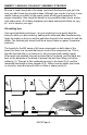
USING THE MX10 POWER L R BASS TREBLE FM-25 HIGHS POWER Above shows a full installation for radio broadcasting using one of the Ramsey micropower transmitters. The parts and pieces are as follows: ❍ MX10, our newly built mixer ❍ STC1, Stereo transmitter companion. Compression, limiting, bass, midrange, and treble controls. Active 8th order lowpass to get rid of interfering sounds. ❍ FM25B, the PLL stereo transmitter.
We sincerely hope you have enjoyed building this kit. We invite you to check out our catalog and see all of the projects that you can put together. We have one of the most complete line of kits available today, and many more products to come. Give us a buzz, well send you a catalog.
The Ramsey Kit Warranty Please read carefully BEFORE calling or writing in about your kit. Most problems can be solved without contacting the factory. Notice that this is not a "fine print" warranty. We want you to understand your rights and ours too! All Ramsey kits will work if assembled properly. The very fact that your kit includes this new manual is your assurance that a team of knowledgeable people have field-tested several "copies" of this kit straight from the Ramsey Inventory.
PROFESSIONAL STEREO MIXER KIT Quick Reference Page Guide Introduction ....................................4 Circuit Description...........................5 MX10 Parts List ............................10 Assembly Procedure.....................11 Schematic Diagram ......................16 Initial Testing.................................23 Troubleshooting ............................24 Layout Diagrams.................26,27,28 Using the MX10 ............................29 Warranty ..............................