
Instruction manual


PA-1 • 10
make a suitable HEATSINK for Q1 and install it before proceeding. A piece of
heavy aluminum or copper the same size as the PA1 circuit board will work fine.
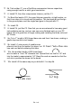
Even when securing Q1 to such a heatsink, do not use too much force. Observe
the correct orientation of Q1 on the actual circuit board when mounting it to the
heatsink. The collector lead (output side) has a 45-degree cut that is plainly
visible.
❒ 14. Pre-tin both the upper and lower surfaces of all four leads of power
transistor Q1.
❒ 15. After reviewing the mounting information, mount Q1 to its heatsink or
section of metal enclosure.
❒ 16. After double-checking the orientation of the collector lead, solder all
four Q1 connections.
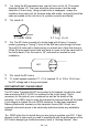
❒ 17a. The final circuit-wiring steps consist of the CORRECT installation of
two small 47 or 56 pf disc capacitors. This step is more critical than many
builders may realize, because excess lead-length of C5 and C6 will reduce
power output and induce feedback! The bodies of C5 and C6 should fit
snug against Q1 and you should see little or no capacitor wire lead at all!
❒ 17b. Install C5 in accord with 17a.
❒ 17c. Install C6, just like C5.
FINAL PC BOARD WIRING BEFORE TESTING:
❒ 18. Solder the 12-volt DC power line connections.
❒ 19a. Use good-quality coax terminated to fittings for your own application.
❒ 19b. Install coaxial input and output lines.
Take a moment now to review your work. Touch up any solder joints that need
to look smoother and shinier. This effort can actually improve performance as
well as make you proud of your work and enhance the resale value of your
amplifier. There should be NO evidence of excessive wire length or rough-
looking solder joints.