
Instruction manual


PA-1 • 5
KIT BUILDING TIPS
Use a good soldering technique - let your soldering iron tip gently heat the
traces to which you are soldering, heating both wires and pads simultaneously.
Apply the solder on the iron and the pad when the pad is hot enough to melt the
solder. The finished joint should look like a drop of water on paper, somewhat
soaked in.
Electrical part installation - when parts are installed, the part is placed flat to the
board, and the leads are bent on the backside of the board to prevent the part
from falling out before soldering. The part is then soldered securely to the
board, and the remaining lead length is then clipped off.
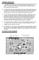
PA1 PARTS LIST:
❒ 1 PA1 Printed circuit board
❒ 1 BLW40 or SD1272 RF Power Transistor
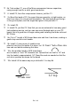
❒ 1 Length of pre-tinned #18 wire (for L1,L2)
❒ 1 Length of #18 enameled wire (for L3)
❒ 1 Length of #24 wire (for winding 6 hole RF choke ferrite bead)
❒ 1 6 hole RF Choke ferrite bead (black cylinder) (to be hand-wound)
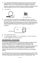
❒ 2 100 pf mica compression trimmers (rectangle shaped) (C1,C3)
❒ 2 60 pf variable trimmer capacitors (round shaped) (C2,C4)
❒ 2 47 or 56 pf ceramic disc capacitors (C5,C6)
❒ 1 .01uf ceramic disc capacitor (marked .01 or 103 or 10 nf) (C7)