
Instruction manual


PA-1 • 6
ASSEMBLY DIRECTIONS:
❒ 1. Simply EXAMINE the PA1 circuit board. Notice which way is up or down
in accord with our published drawing. Notice that ALL components are
surface-mounted (tack-soldered) to one side of the PC board. There are
NO component-mounting holes!
❒ 2. Taking care that your soldering tip is clean, pre-tin all mounting pads on
the board. You are using enough heat if the solder flows VERY easily and
remains shiny. That is the only acceptable result. A smooth build-up of
solder thickness is fine and will make parts installation even easier.
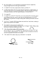
❒ 3. The power transistor will be installed as a later step. Right now, simply
position it in place and observe how far its flat leads extend toward the
input and output pads. Scribe a line into the tinned pads at each end of
these two leads as a guide to the amount of pad space required by the
transistor. NOTICE THE ORIENTATION OF THE TRANSISTOR'S
COLLECTOR LEAD! Set the transistor aside for now, safely.
❒ 4. In installing the coils leading in and out of the transistor's pads, the idea
is to stay on the other side of your marks, so that the transistor can be
installed flat and neatly on the board.
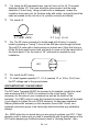
❒ 5a. Examine C1, one of the mica compression trimmers. Neatly re-form the
two outer tabs at right angles so they form "feet" which permit the trimmer
to sit level in its correct position. Make sure the inner pins do not touch the
PC board.
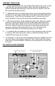
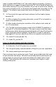
PA1 PARTS LAYOUT DIAGRAM