RV1 REVERB EFFECTS/ SURROUND SOUND KIT Ramsey Electronics Model No. RV1 Tired of listening to the same old tired sound from your TV or VCR? Want something to impress your friends on the radio? Do you like awesome effects on your voice when you speak or sing? This kit is for you! With this fully configurable kit, you can do these things and more, with impressive results! • Variable delay times, from ½ second to no delay.
RAMSEY TRANSMITTER KITS · FM100 Professional FM Stereo Transmitter · FM25 Synthesized Stereo Transmitter ·AM1, AM25 AM Transmitters · TV6 Television Transmitter RAMSEY RECEIVER KITS · FR1 FM Broadcast Receiver · AR1 Aircraft Band Receiver · SR2 Shortwave Receiver · AA7 Active Antenna · SC1 Shortwave Converter RAMSEY HOBBY KITS · SG7 Personal Speed Radar · SS70A Speech Scrambler · ECG1 Heart Monitor · WCT20 Wizard Cable Tracer · PG13 Plasma Generator · LABC1 Lead Acid Battery Charger RAMSEY AMATEUR RADIO KI
Ramsey Publication No. MRV1 Price $5.00 KIT ASSEMBLY AND INSTRUCTION MANUAL FOR RV1 REVERB EFFECTS & SURROUND SOUND KIT TABLE OF CONTENTS Introduction to the RV1 ................. 4 Circuit description ......................... 5 Parts list ........................................ 7 RV1 Assembly instructions ........... 9 Jumper installation ....................... 15 Initial testing ................................ 16 Troubleshooting ........................... 17 Using the RV1 ..........................
RV1 REVERB EFFECTS AND SURROUND FEATURES: • Fully configurable for several different modes of use • Several adjustments for a wide range of effects from a "chorus" sound, down to an "outer space" sound • Configurable as a stand alone unit with speaker audio output and microphone input • Configurable for audio line level processing • Very impressive surround sound effect; makes speakers seem as if they are all around you.
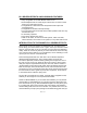
find the problem and are able to correct it. CIRCUIT DESCRIPTION: Referring to the schematic diagram, you will see the basic layout to the circuit. You will notice that there are many jumpers in the circuit as well. These jumpers allow the kit to be configured for various applications. For now we will talk about using the kit as a surround sound processor, which requires only JMP 5, and JMP 7 to be in place, and all others left out.
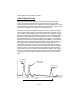
For the surround effect, the output of U1:C, the lowpass filter is sent into an inverting amplifier to give a signal which is 180 degrees out of phase with the output of the lowpass filter. When sent into the right channel, this audio will cancel some of the audio from the left channel at your ears when played though your speakers. Since the audio that is canceled is from the delayed sound, not the original sound, it produces an interesting effect of "widening" the placement of you speakers.
RAMSEY RV-1 REVERB EFFECTS PARTS LIST: SEMICONDUCTORS [ [ [ [ ]1 ]1 ]1 ]1 LM324 Quad opamp [U1], 14 pin MN3101 Clock generator driver for BBD [U2], 8 pin MN3007 1024 Step Bucket Brigade Device [U3], 8 pin LM386 audio amplifier [U4], 8 pin CAPACITORS [ [ [ [ [ [ [ ]2 ]2 ]1 ]1 ]1 ] 10 ]2 .01uF disc ceramic (marked .01 or 103 or 10 nF) [C7,17] .005uF disc ceramic (marked .005 or 502 or 5 nF) [C5,6] .1uF disc ceramic (marked .
RAMSEY "LEARN-AS-YOU-BUILD RECORDER ASSEMBLY STRATEGY" The RV1 has a fairly compact assembly compared to some of our kits, and for this reason it is advisable to follow our step by step instructions closely. The reason being that if you were to install some of the larger components first, there would be no room to get your fingers in to install some of the smaller components later.
CONSTRUCTION OF THE RV1 REVERB EFFECTS KIT: The first thing we will do with this kit is check all of our parts and pieces to make sure we have them all. Use the parts list to do this. If there are any differences, make sure the schematic agrees with what you have, and also be aware of the tolerances parts have in a kit. Non-critical parts can vary quite a bit with almost no effect on kit operation. For example you may get 1uF capacitors in place of 10uF capacitors, or a 100K pot in place of a 10K pot.
[ ] 11. Install C19, a 10uF electrolytic capacitor. Be sure and check the orientation before you solder it into place. [ ] 12. Install R1 a 4.7K resistor (yellow-violet-red). [ ] 13. Install R2, a 100K resistor (brown-black-yellow). [ ] 14, install R35, a 4.7K resistor (yellow-violet-red). [ ] 15. Install R36, one of your 200K ohm trimmer pots. This part combined with R35, and C19 controls how much feedback is allowed back into the inputs.
[ ] 23. Welcome back! Now we are ready to install R27, a 5.6K resistor (green-blue-red). Some resistors have a 2% tolerance, so the band colors are green-blue-red-red, the last band denoting the 2% tolerance. Be careful as sometimes you may confuse it for another resistor value by reading the lines backwards. [ ] 24. Install R26, another 5.6K resistor (green-blue-red). [ ] 25. Install C8, a 10uF electrolytic capacitor.
combined with R28, and R31 form a voltage divider to split the supply voltage so that the opamps can be used on a single supply such as a battery. It is slightly less than one half of supply so that there is plenty of room for distortion free sound in the opamps and the BBD. [ ] 37. Install C13, a 10uF electrolytic capacitor. Pay close attention to the orientation again. [ ] 38. Install R30, a 10K pot. This pot will control the attenuation if you are to configure your kit to have a speaker output. [ ] 39.
[ ] 47. Install C6, another .005uF ceramic capacitor (marked 5nF, .005, or 502). [ ] 48. Install R7, another 39K resistor (orange-white-orange). [ ] 49. Install C7, a .01uF ceramic capacitor (marked 103 or .01) [ ] 50. Install R34, a 100K resistor (brown-black-yellow). [ ] 51. Install R13, a 4.7K resistor (yellow-violet-red). [ ] 52. Install R8, a 33K resistor (orange-orange-orange). [ ] 53. Install C1, a 470pF ceramic capacitor (marked 470 or 471).
RV-1 • 14
[ ] 64. Install U4, the chip marked 386 (8 pin dip). Pay close attention to it's orientation and where pin 1 is. This is the audio amplifier chip, and is used in many of the Ramsey kits. [ ] 65. Install C17, a .01uF ceramic capacitor (marked .01, 10nF, or 103). [ ] 66. Install C14, a 220uF to 470uF electrolytic capacitor. This value isn't entirely critical, but it prevents the power amp from causing the circuit to oscillate from its current draw on the battery.
JUMPER INSTALLATION: This is a point in your kit where you will make a decision in how you wish to configure your kit. There are several different configurations, and we will chart them for you. [ ] CONFIGURING INPUTS: (concerning JMP2, JMP3, JMP4) Surround sound for Hi-Fi: • Install none or... • Install none and remove R4 and R1 to add to the "rear channel" effect. Stereo sound from mono source (such as VCR): • Install JMP2, all others out. Mono microphone source: • Install JMP3, JMP4, all others out.
INITIAL TESTING: To begin our initial tests, we need only a few missing pieces to complete the whole reverb kit. • A good 9VDC source such as a battery or a regulated supply. Any power supply may be used, but if of low quality, may introduce hum the circuit. into • Suitable connectors for power, speaker, mike or RCA to RCA connectors. • A speaker, stereo receiver, or mike. [ ] 1. Verify that all parts are mounted and soldered in the correct places. [ ] 2. Make sure the power switch is turned off.
If any of these steps did not work as described, go to the trouble-shooting section of the manual to determine how to resolve the problem.
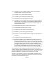
For vocal effects: M ic ro p h o ne R V 1 L R T o m ic i t S peak For stereo simulation: Mono source Microphone or VCR VCR RV-1 L R Amplifier L R RV-1 • 19
RV-1 PARTS LAYOUT DIAGRAM RV-1 • 20
RV-1 PART VALUE DIAGRAM RV-1 • 21
The Ramsey Kit Warranty Please read carefully BEFORE calling or writing in about your kit. Most problems can be solved without contacting the factory. Notice that this is not a "fine print" warranty. We want you to understand your rights and ours too! All Ramsey kits will work if assembled properly. The very fact that your kit includes this new manual is your assurance that a team of knowledgeable people have field-tested several "copies" of this kit straight from the Ramsey Inventory.
RV-1 REVERB AND SURROUND EFFECTS Quick Reference Page Guide Introduction to the RV-1 ................... Circuit description ............................. Parts list ............................................ RV-1 Assembly instructions.............. Initial testing...................................... Troubleshooting ................................ Using the RV-1 ................................. Parts Layout diagram ....................... Parts value diagram..........................