Electronic Cricket Sensor Ramsey Electronics Model No. ECS1 What’s that peeping? Must be the crickets outside. Wait, no it’s the ECS1! Tell the temperature by counting the chirps. An easy to build kit for all ages . What fun is it to look at a thermometer, I ask you! Get a cricket and have a fun conversation piece! • Works as a thermometer just like a real cricket • Tells temperature by the rate of chirping • Runs on a 9V battery.
PARTIAL LIST OF AVAILABLE KITS: RAMSEY TRANSMITTER KITS • FM10A, FM25B FM Stereo Transmitters • AM1, AM25 Transmitter • PPM3 Phone Patch Mixer RAMSEY RECEIVER KITS • FR1 FM Broadcast Receiver • AR1 Aircraft Band Receiver • SR2 Shortwave Receiver • AA7 Active Antenna • SC1 Shortwave Converter RAMSEY HOBBY KITS • SG7 Personal Speed Radar • SS70A Speech Scrambler/Descrambler • TT1 Telephone Recorder • WEB1 Walking Electronic Bug • UAM2 20W Audio Amplifier • PG13 Plasma Generator • MD3 Microwave Motion Detector
Ramsey Publication No. ECS1 Manual Price Only $5.00 KIT ASSEMBLY AND INSTRUCTION MANUAL FOR Electronic Cricket Sensor TABLE OF CONTENTS Introduction to the ECS1 ................................... 4 ECS1 Circuit Description ................................... 4 “Learn-As-You-Build” Kit Assembly.................... 6 Parts List............................................................. 7 Assembly Steps.................................................. 8 ECS1 Parts Layout Diagram .........................
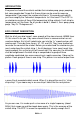
INTRODUCTION Everyone has heard the crickets outside their window peep, peep, peeping, but some people don’t know that those chirps can be used to measure temperature! If you count the number of chirps in 15 seconds and add 40, you have roughly the Fahrenheit temperature. Isn’t that swell? The ECS1 is an electronic version of those little temperature telling crickets. It will chirp to temperature just like them. So all you do is build it, tweak it, then: peep, peep peep, “Hey it’s 72 degrees out”.
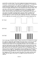
sounds like a cricket chirp. The circuit responds to temperature by way of a thermistor, a resistor whose value changes with temperature. The thermistor is used as a timing resistor in U1. When the temperature changes, U1’s output frequency changes and so does the cricket chirp rate. In order to keep the circuit simple and inexpensive, some compromises had to be made. The main one is that the circuit is composed of elements that produce square waves, not sine waves.
RAMSEY Learn-As-You-Build KIT ASSEMBLY There aren’t that many solder connections on the ECS1 printed circuit board, but you should still practice good soldering techniques. • • • • Use a 25-watt soldering pencil with a clean, sharp tip. Use only rosin-core solder intended for electronics use. Use bright lighting; a magnifying lamp or bench-style magnifier may be helpful. Do your work in stages, taking breaks to check your work.
ECS1 PARTS LIST Sort and “check off” the components in the boxes provided. We do our best to pack all our kits correctly but it is possible that a mistake has occurred and we missed a part. Please note that physical descriptions of parts are for those currently being shipped. Sometimes the parts in your kit may have a different appearance but still have the same values.
ECS1 PC BOARD ASSEMBLY STEPS 1. Take a look at the layout diagram. Let’s start with the bottom left of the board and install power switch S1. Be sure to use enough solder to firmly attach it to the board. 2. Next, install D2, 1N4148 diode, to the right at the bottom of the board. Be sure it goes in the right way. Line up the black band on the part with the white band on the board drawing. 3. Install R2, 500K potentiometer [marked 504], to the right of D2. 4. Install R3, 100K thermistor, next to R2.
15. Install D4, 1N4148 silicon diode, above C5. Watch the polarity. 16. Install R5, 1K ohm resistor [brown-black-red], above D4. 17. Install D3, 1N4148 diode, right next to R5. Once again, don’t put it in backwards just to be a rebel. 18. Install R4, 100K resistor [brown-black-yellow], next to D3. 19. Install R6, 470 ohm resistor [yellow-violet-brown], next to R4. 20. Install U2, 555 timer IC under R4. Line up the notch like you did with U1. 21. Install C3, .
ECS1 BOARD PARTS LAYOUT DIAGRAM ECS1• 10
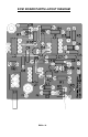
ECS1 MAIN BOARD SCHEMATIC ECS1• 11
SETUP AND TESTING Plug a 9V battery into the connector. You should hear some chirps coming out of the speaker. Turn R9 to adjust volume. Now turn R7 slowly to get the pitch that you think sounds most like a cricket. In addition you can remove one or both capacitors C9 and C10. This will change the sound more, but will also reduce volume. When you get the sound the way you like it, you need to calibrate the ECS1 so that it will chirp to the right frequency.
CONCLUSION We sincerely hope that you will enjoy the use of this Ramsey product. As always, we have tried to compose our manual in the easiest, most “user friendly” format that is possible. As our customers, we value your opinions, comments, and additions that you would like to see in future publications. Please submit comments or ideas to: Ramsey Electronics Inc. Attn. Hobby Kit Department 590 Fishers Station Drive Victor, NY 14564 or email us at: techsupport@ramseymail.
ECS1• 14
The Ramsey Kit Warranty Please read carefully BEFORE calling or writing in about your kit. Most problems can be solved without contacting the factory. Notice that this is not a "fine print" warranty. We want you to understand your rights and ours too! All Ramsey kits will work if assembled properly. The very fact that your kit includes this new manual is your assurance that a team of knowledgeable people have field-tested several "copies" of this kit straight from the Ramsey Inventory.
ECS1 Quick Reference Page Guide ECS1 Circuit Description................................... 4 Parts List............................................................. 7 ECS1 Parts Layout Diagram ............................ 10 ECS1 Schematic .............................................. 11 Setup and Testing ........................................... 12 Ramsey Kit Warranty .......................................