ION CANNON ION GENERATOR KIT Ramsey Electronics Model No. IG7 Have you ever wondered how those ion air cleaners work? Ever wonder why the air smells so fresh after a thunderstorm? This instructional manual takes you through several ion related experiments that you can play with to see for yourself how amazing ions are, their health benefits, and health risks. Also make a working air cleaner for the water closet when done! • ION power supply with adjustable control for a clean source of high voltage DC.
RAMSEY TRANSMITTER KITS • FM100B Professional FM Stereo Transmitter • FM25B Synthesized Stereo FM Transmitter • MR6 Model Rocket Tracking Transmitter • TV6 Television Transmitter RAMSEY RECEIVER KITS • FR1 FM Broadcast Receiver • AR1 Aircraft Band Receiver • SR2 Shortwave Receiver • SC1 Shortwave Converter RAMSEY HOBBY KITS • SG7 Personal Speed Radar • SS70A Speech Scrambler • BS1 “Bullshooter” Digital Voice Storage Unit • AVS10 Automatic Sequential Video Switcher • WCT20 Cable Wizard Cable Tracer • LABC1 L
Ramsey Publication No. MIG7 Price $5.00 KIT ASSEMBLY AND INSTRUCTION MANUAL FOR IG7 ION CANNON ION GENERATOR KIT TABLE OF CONTENTS Safety Guidelines .................................4 Ion Theory .............................................6 Learn As You Build .............................13 Parts List .............................................15 Assembly .............................................16 Parts Layout ........................................20 Schematic....................................
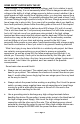
SOME SAFETY NOTES WITH THE IG7 Even though 7.5 kV sounds like a lot of voltage, and it is in relation to most other circuitry today, it is not necessarily lethal. What is dangerous about high voltage is the ability of a high voltage source to deliver current, whether it be a quick impulse of high current like a lightning strike, or a long term source like a high voltage power supply.
• NEVER EVER! charge capacitors unless you honestly know what you are doing! This increases the danger level astronomically! Even a small high voltage capacitor when charged can deliver more than enough current to kill or injure you! • Keep a clean workbench. Having a clutter of wires around can confuse you as to which ones are actually grounded, and which ones you may use to try and discharge the high voltage terminal.
ION THEORY What are ions you may ask, are they protons or electrons? Actually they are neither one, at least not electrons by themselves. An ion is a charged molecule like that of a particle of smoke which either has one or more electrons removed, or one or more extra electrons added giving it the ability to carry a charge of electricity.
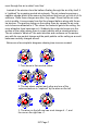
ment through the air is called ‘ionic flow’. Instead of the electron from the balloon floating through the air all by itself, it is “grabbed” by a passing neutral air molecule. The air molecule acquires a negative charge which is the same as the balloon that has not yet lost all of it’s electrons. Since these charges are alike, they repel. Given that the air molecule is mobile, it moves away from the like charged balloon along with the extra electron.
The previous diagrams show how ions are created by contacting two atoms together and thereby handing off an electron. If these atoms were mobile like in a gas or liquid, the different charges would attract each other very quickly and neutralize again. They wouldn’t get very far at all unless the atoms had enough velocity to overcome the electrical attraction.
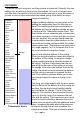
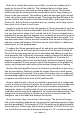
The diagram below shows a conductive tear-shaped object with a high voltage field around it. The lines are called equipotential lines and they indicate our voltage gradient potential as we mentioned before. A rounded tip will disperse the gradient over a larger area than that of a sharp tip. Notice below that the gradient on a rounded tip isn’t very steep while the sharper tip is.
When air is ionized during the corona effect, you will see a sharp point of purple on the end of the metal tip. This indicates that air is either being stripped of electrons or electrons are being added to the air. The process emits some light as the electrons are moved about due to them jumping valences in the gas molecule. The problem is when air becomes highly ionized, it also can become quite reactive as well.
cation. In our case the terminal will be around 3 to 5 kV with the IG7. How do we reduce the potential energy of these charged ions to make it safer for electrical components? We use a simple device called an ion tube. Ion Tubes Ion tubes serve a few special functions and are luckily easy to construct. A tube consists of a grounded piece of conductive tubing with a sharp pin that is centered at one end to emit the high voltage ions we are looking for.
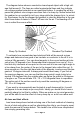
Believe it or not, there are always ions around you. They are created by numerous methods, most notably: radioactive decay, solar radiation, friction between dissimilar materials such as air and land, and materials like water changing state from water to ice and water to gas. Some of these methods combine to fuel lightning which we see during a storm. These provide plenty of ionic flow besides the actual lightning strikes. A very good book on this subject is called Nature’s Electricity written by Charles K.
RAMSEY “LEARN-AS-YOU-BUILD” ASSEMBLY STRATEGY Be sure to read through all of the steps, and check the boxes as you go to be sure you didn't miss any important steps. Although you may be in a hurry to see results, before you switch on the power check all wiring and components for proper orientation. Also check the board for any possible solder shorts, and/or cold solder joints.
Since this is a High Voltage product, we sincerely hope you put this together in a professional manner. This project will not work as well as you wished if you just slap it together without following good assembly techniques and all the instructions. No matter how clear we may think our manual is, if you have any questions, give us a call at the factory instead of jumping to conclusions. We will be happy to help you with any problems.
RAMSEY IG7 PARTS LIST Supplies 1 ...HVDC-1 7.5 kV Ion power supply 1 ...PC Board with 7 large holes 1 ...PC Board with 5 large holes 1 ...Base mounting PC board 4 ...L Brackets 7 ...#16 Nails, 1 1/4” long 4 ...Large rubber feet 1 ...small size LED (for HV indicator) 1 ...1K Ohm resistor (brown-black-red) 1 ...2.1 mm Power jack 7 ...1/2 Inch copper pipe couplers 2 ...#4 x 1/4” sheet metal screws 8 ...#4 x 3/16” machine screws 1 ...
ASSEMBLY Assembly of you Ion Cannon is pretty simple. It does however require a pretty hot soldering iron and some patience. Most of this kit is mechanical in nature so think of it more like an erector set. 1. We will begin by assembling the most difficult item first in order to get it out of the way. This requires a bit of solder and a lot of patience to make it look good. Please don’t rush this part. For this step you will need the seven couplers and the board with the seven holes in it.
4. Set aside the pipe and board assembly. We will now work on the nail (pin elements) assembly. 5. First thing first we are going to sharpen these nails. There are plenty of ways to sharpen nails but the easiest way is to use fine file to round and sharpen the points. Remember the sharper the better! It can take a while to get a good sharp point at the very tip so take your time. Note that nails are typically not extremely hardened steel so you wont get a tip that could cut an atom in two.
10. Install D1, the LED. Note that this is one of the exceptions to the rule, you want to leave the leads as long as possible! You want the LED to stand up at least 3/4” off of the board when you solder it in place. We will later bend over the leads so that the LED will poke its little head out of the front panel pipe assembly board.
Attaching the Boards To the Main Board 21. Now solder the final larger white wire of the Ion Generator to the bare pad provided on the back side of the nail board in the upper right corner. 22. Check nail positions within the copper tubes and make sure they are approximately centered. They don’t have to be right in the middle but if they are cocked at an angle, you may wish to heat up the solder and reposition the nail to center it properly.
Parts Layout MAIN BOARD NAIL BOARD PIPE BOARD IG7 Page 20
IG7 Page 21
EXPERIMENTS On a personal note; back when I was in Junior High School, I really wished kits like this were available. I always loved tinkering with high voltage and seeing the strange phenomenon associated with high voltage and high power. Maybe this was a fixation with fire... or maybe something else (Froyd could better answer than I can).
ION CANNON Once the Ion Cannon has been assembled according to the previous directions. We’ll need to find a suitable place to run the Ion Cannon project. Select a location that is not near sensitive electronics components and has easy access to power so that you don’t have to reach across the running unit to turn off the power.
Lets try some fun stuff now. Take the small neon light included with your kit and hold on to one of the leads. Point the other lead towards the tubes in the path of the discharged air. DO NOT STICK THE LEAD INTO THE TUBES! If you look closely, you should be able to see the neon light periodically flashing. This indicates that the air coming out of the pipes retains at least 60 volts of charge which is going through the bulb and in to you! You don’t feel this because the current is very small.
mean there are no ions present, just that their potential is too low. The next experiment requires some objective observing. You will need to put your Ion Cannon in a place that normally contains a lot of bad smells like in the garage over the garbage can, or in the bathroom near the porcelain throne. Note the smell before and after you run the Ion Cannon.
Pinwheel (Corona Motor) The Pinwheel experiment is the old standby experiment that demonstrates ionic flow as well as Newton’s 3rd law of Motion: “For every action there is an equal and opposite reaction”. When we expend ions off into the air with our Ion Cannon, we are not only pushing air out of the ends of the pipes, but we are also pushing the Ion Cannon in the opposite direction.
12. Power up the Ion Generator, and watch the motion of the rotor! This demonstrates how ions can be used for propulsion! In fact NASA has employed this process on some space crafts to help them maneuver in outer space. Ion propulsion is used to slowly reposition the craft, and also assist in acceleration.
This page has been left blank so you may cut the pinwheel template out of the manual without losing any juicy information!! IG7 Page 28
TROUBLESHOOTING PROBLEM: The LED doesn’t light up. SOLUTION: Not much that can go wrong in this circuit. Double check your solder connections again. It is quite possible you have a dead short someplace so you had better check it out without the power applied! This is most likely caused by the diode orientation. Check the Flat side against the silk screen. PROBLEM: The LED lights, but no high voltage. SOLUTION: There is probably an assembly problem.
CONCLUSION We sincerely hope that you enjoy the use of this Ramsey product. As always, we have tried to compose our manual in the easiest, most user-friendly format that is possible. As our customers, we value your opinions, comments, and additions that you would like to see in future publications. Please submit comments or ideas to: Ramsey Electronics Inc. Attn. Hobby Kit Department 590 Fishers Station Drive Victor, NY 14564 Please feel free to visit our Website at www.ramseyelectronics.
The Ramsey Kit Warranty Please read carefully BEFORE calling or writing in about your kit. Most problems can be solved without contacting the factory. Notice that this is not a "fine print" warranty. We want you to understand your rights and ours too! All Ramsey kits will work if assembled properly. The very fact that your kit includes this new manual is your assurance that a team of knowledgeable people have field-tested several "copies" of this kit straight from the Ramsey Inventory.
IG7 ION CANNON KIT Quick Reference Page Guide Safety Guidelines .................................4 Ion Theory .............................................6 Parts List .............................................15 Assembly .............................................16 Parts Layout ........................................20 Schematic ............................................21 Experiments ........................................22 Troubleshooting...................................29 Warranty .........