
Instruction manual


IG7 Page 17
4. Set aside the pipe and board assembly. We will now work on the nail (pin
elements) assembly.
5. First thing first we are going to sharpen these nails. There are plenty of
ways to sharpen nails but the easiest way is to use fine file to round and
sharpen the points. Remember the sharper the better! It can take a while to
get a good sharp point at the very tip so take your time. Note that nails are
typically not extremely hardened steel so you wont get a tip that could cut
an atom in two. It is however sharp enough for our purposes. How sharp is
sharp enough? You can test the end by poking your finger and if it hurts…
it’s sharp… Duh! The other way is to look at the end with a magnifying lens
so you can clearly see how well you have sharpened the tip. Probably the
preferable way!
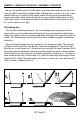
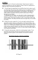
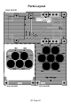
6. The next step is to mount the seven nails being used as our electrode
elements. We want the nails to point straight out from the board as they will
be positioned with the points inside the ion tubes. Insert the nails from the
solder side of the PCB with the 5 large holes. It is labeled with Nail1 - Nail7
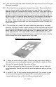
on the opposite side. You might want to scrape away a little more of the
green resist layer from around the nail holes to make them easier to solder
with the head flush to the copper side of the board.
7. Solder all seven nails into place. This does take some decent heat as
the nails have a zinc coating that makes it a bit difficult to solder to. Once
they are hot enough though, the solder will flow.
8. Set the nail assembly aside for now and let’s begin work on the main
board assembly. We will start with the small components and go up from
there.
9. Install R1, the 1K ohm resistor (brown-black-red). This resistor is used
to limit current through the front panel LED. ensuring that is runs at the
correct brightness. Hey, a little circuit theory always helps!
Solder Example of the Nail Installation