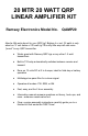
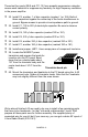
20 MTR 20 WATT QRP LINEAR AMPLIFIER KIT Ramsey Electronics Model No. QAMP20 Need a little extra boost for your QRP rig? Believe it or not, 20 watts is only about an ‘S’ unit below a 100 watt rig! This nifty little amp will add some “punch” to any QRP transmitter.
RAMSEY TRANSMITTER KITS • FM10A, FM25B FM Stereo Transmitters • TV6 Television Transmitter • Cube TV Transmitters RAMSEY RECEIVER KITS • FR1 FM Broadcast Receiver • AR1 Aircraft Band Receiver • SR2 Shortwave Receiver • AA7 Active Antenna • SC1 Shortwave Converter RAMSEY HOBBY KITS • SG7 Personal Speed Radar • SS70A Speech Scrambler • TT1 Telephone Recorder • SP1 Speakerphone • MD3 Microwave Motion Detector • PH10 Peak hold Meter • LC1 Inductance-Capacitance Meter RAMSEY AMATEUR RADIO KITS • DDF1 Doppler Dir
Ramsey Publication No. MQAMP20 Price $5.00 KIT ASSEMBLY AND INSTRUCTION MANUAL FOR 20 METER QRP CW POWER AMPLIFIER KIT TABLE OF CONTENTS Introduction to the QAMP20........... 4 How it works................................... 4 Parts list ......................................... 5 Learn as you Build ......................... 6 QAMP20 assembly instructions ..... 7 Initial tests ..... .............................. 12 Verifying RF output power ........... 13 Troubleshooting tips.....................
INTRODUCTION The Ramsey QAMP series of QRP power amplifiers are compact 10 to 20 watt RF amplifiers for QRP CW transmitters. These amplifiers are made to be driven by transmitters in the ½ to 2 watt range. Built-in to the power amplifier is a sensitive T-R relay which will switch the unit in and out of the antenna line. When in receive, the amplifier is bypassed and the antenna feeds directly to the input jack.
PARTS LIST FOR THE QAMP20 QRP POWER AMPLIFIER CAPACITORS: 1 1 4 2 2 2 1 100 to 220 µf electrolytic capacitor [C1] 10 µf electrolytic capacitor [C2] .1 µf disc capacitors (marked .1 or 104) [C3,8,10,13] 180 ρf disc capacitors (marked 180 or 181) [C4,7] 330 ρf disc capacitors (marked 330 or 331) [C5,6] .001 µf disc capacitors (marked .001 or 102 or 1000) [C11,12] .01 µf disc capacitor (marked .
REQUIRED, NOT SUPPLIED: Ramsey case, knob and panel set, Ramsey part no. CQRP Matching input and output cables to existing QRP transmitter 12 volt DC power supply 3 amp rating Proper dummy load or resonant antenna "THE RAMSEY LEARN-AS-YOU-BUILD ASSEMBLY STRATEGY" Take a look at the parts layout diagram. There is quite a lot to the construction of the QAMP20. It's easier than it seems once you get going, especially after you have installed a few of the "landmark" components.
In all the following instruction steps, our word "INSTALL" means to do the following: • Insert the part, oriented correctly, into its correct holes in the PC board. • If helpful, gently bend the part’s wire leads or tabs to hold it in place, with the body of the part snugly against the top side (component side) of the PC board. • Solder all wires or pins of the part, whether the 2 wires of a resistor or the 3 or 4 wires of a transistor.
15. Install Q3 and Q4, 2N3904 NPN transistors, observing proper orientation of the flat side. These two transistors amplify the signal diode's output to a level high enough to close relay K1. 16. Install diode D4, 1N4002 style black epoxy diode. Check positioning of the banded end. 17. Install jumper JMP2. Use a piece of scrap component lead wire bent into a "staple" shape and inserted into the board like a component.
These last four parts (R8,9 and C11,12) form parasitic suppression networks across each transistor to suppress any tendency for high frequency oscillation in the power amplifier. 32. Install C3, another .1 µf disc capacitor (marked .1 or 104). Both of these capacitors bypass the center tap of the ferrite transformers to ground. Bypass means to provide a low impedance path to ground. 33. Install C1, 100 to 220 µf electrolytic capacitor. Be sure to observe correct polarity. 34.
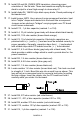
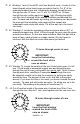
41. Winding L1 and L3 toroid RF coils (two identical units ): Locate 2 of the donut shaped yellow toroid cores provided in the kit. Cut 8" of the enameled magnet wire and, following the drawing, thread the wire through the core 12 times - not 11, not 13; it MUST be 12 times through the core, pulling each turn gently tight. Winding too tightly runs the risk of scraping off the enamel insulation and shorting the wire.
through the core, continuing on in the same direction as before. Tin each end with solder all the way up to the core body. This winding is the 2 turn center-tapped secondary of T2. 45. Winding T1: Locate the remaining larger 2-hole ferrite core. Cut off a 10 inch length of the enameled magnet wire and thread the wire through the core 3 times, pulling each turn gently tight. That's 3 times through each hole resulting in 3 complete turns through the core.
50. Install L2, the 14 turn toroid inductor - you marked it special, remember? 51. Install L3, the remaining 12 turn toroid inductor. This completes the assembly of your QRP power amplifier. Now's a good time to give your masterpiece a good going over, being especially alert for any: • • • • bridged-over solder joints; misplaced components; transistors or diodes placed wrong; electrolytic capacitors installed wrong. INITIAL TESTS: To prepare your amplifier for testing you'll need the following: • 1.
4. Temporarily install a jumper from the collector of Q3 to ground. 5. Apply power to the amplifier but do not turn on the transmitter. Measure the current drawn by the amplifier and slowly rotate the bias pot, R4, clockwise until you reach a reading of ¼ amp. Do not allow the current to rise above ½ amp. If you cannot adjust or reduce the current, disconnect the power supply and consult the troubleshooting hints section. The voltage at TP1 should be about 3.2 to 3.5 volts. 6. Turn off power.
Ideally, you have a small RF wattmeter, already inserted in the antenna line, capable of accurately measuring low output power in watts. And it cost you less than what you paid for the transmitter kit. Right? In the words of Wayne from "Wayne's World"... Not! So here are a few other ideas for you to try. Saying the same thing another way, we assume you know that accurate, commercially built RF wattmeters cost much more than what you paid for this Ramsey amplifier kit.
KB4ZGC on how to make a highly accurate yet inexpensive dummy load and wattmeter capable of showing 1/10-watt differences in RF power. If you use a wattmeter characterized for the HF frequency region, it will not give accurate results at the much higher two meter frequencies, although it will be quite adequate for go/no-go testing.
If you hear an AC hum on the transmitted signal, usual causes are RF getting back into the power supply or a bad VSWR on the antenna. These short checks in no way detail any and all problems that can rear their ugly head, but should get you on the way to solving most errors. We'd like to be able to foresee a problem a builder may encounter, but the sheer number of parts and the permutations and combinations of installing them makes any list of precise, exact solutions impossible.
While we believe that the Ramsey enclosure and knob option is a fine value for finishing off your Ramsey kit, we are happy to give you a couple of additional suggestions and our reasons for them. If your first goal is economy and rugged portability, you will find that the circuit board can be mounted nicely in a standard VHS videotape storage box, which also gives room for storing cables, a small homemade keyer, etc. The controls are easily mounted at one end of such a box.
QAMP20 • 18
The Ramsey Kit Warranty Please read carefully BEFORE calling or writing in about your kit. Most problems can be solved without contacting the factory. Notice that this is not a "fine print" warranty. We want you to understand your rights and ours too! All Ramsey kits will work if assembled properly. The very fact that your kit includes this new manual is your assurance that a team of knowledgeable people have field-tested several "copies" of this kit straight from the Ramsey Inventory.
QAMP20 20 WATT LINEAR AMPLIFIER Quick Reference Page Guide How it works ................................... 4 Parts list .......................................... 5 Learn as you Build .......................... 6 QAMP20 assembly instructions ..... 7 Initial testing ..... ........................... 12 Verifying RF output power ............ 13 Using the QAMP20 ....................... 16 Parts layout diagram .................... 17 Schematic diagram ....................... 18 Ramsey kit warranty ............