30 MTR 20 WATT QRP LINEAR AMPLIFIER KIT Ramsey Electronics Model No. QAMP30 Need a little extra boost for your QRP rig? Believe it or not, 20 watts is only about an ‘S’ unit below a 100 watt rig! This nifty little amp will add some “punch” to any QRP transmitter.
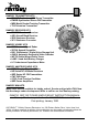
RAMSEY TRANSMITTER KITS • FM100B Professional FM Stereo Transmitter • FM25B Synthesized Stereo FM Transmitter • MR6 Model Rocket Tracking Transmitter • TV6 Television Transmitter RAMSEY RECEIVER KITS • FR1 FM Broadcast Receiver • AR1 Aircraft Band Receiver • SR2 Shortwave Receiver • SC1 Shortwave Converter RAMSEY HOBBY KITS • SG7 Personal Speed Radar • SS70A Speech Scrambler • BS1 “Bullshooter” Digital Voice Storage Unit • AVS10 Automatic Sequential Video Switcher • WCT20 Cable Wizard Cable Tracer • LABC1 L
Ramsey Publication No. MQAMP30 Price $5.00 KIT ASSEMBLY AND INSTRUCTION MANUAL 30 METER QRP CW POWER AMPLIFIER KIT TABLE OF CONTENTS Introduction to the QAMP30........... 4 How it works................................... 4 Parts list ......................................... 5 Tips and notes ............................... 6 QAMP30 assembly instructions ..... 6 Initial testing ..... ........................... 12 Verifying RF output power ........... 13 Troubleshooting tips.....................
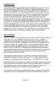
INTRODUCTION The Ramsey QAMP series of QRP power amplifiers are compact 10 to 20 watt RF amplifiers for QRP CW transmitters. These amplifiers are made to be driven by transmitters in the ½ to 2 watt range. Built-in to the power amplifier is a sensitive T-R relay which will switch the unit in and out of the antenna line.
PARTS LIST FOR THE QAMP30 QRP POWER AMPLIFIER CAPACITORS: 1 100 to 220 µf electrolytic capacitor [C1] 1 10 µf electrolytic capacitor [C2] 4 .1 µf disc capacitor (marked .1 or 104) [C3,8,10,13] 2 330 ρf disc capacitor (marked 330 or 331) [C4,7] 2 560 ρf disc capacitor (marked 560 or 561) [C5,6] 2 .001 µf disc capacitor (marked .001 or 102 or 1000) [C11,12] 1 .01 µf disc capacitor (marked .01 or 103 or 10 nf) [C9] RESISTORS: 3 1 K ohm resistor (brown-black-red) [R1,5, TP1] 1 6.
"THE RAMSEY LEARN-AS-YOU-BUILD ASSEMBLY STRATEGY" Take a look at the parts layout diagram. There is quite a lot to the construction of the QAMP30. It's easier than it seems once you get going, especially after you have installed a few of the "landmark" components. Once these "landmark" components are placed, other parts’ positions are referenced to them, and construction goes quite smoothly.
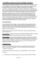
• • • If helpful, gently bend the part’s wire leads or tabs to hold it in place, with the body of the part snugly against the top side (component side) of the PC board. Solder all wires or pins of the part, whether the 2 wires of a resistor or the 3 or 4 wires of a transistor. Trim all excess wires extending beyond each solder connection, taking care that wire trimmings do not become lodged in PC board solder connections. 1. Install S1, PC mount pushbutton switch. Solder all 6 pins securely. 2.
16. Install diode D4, 1N4002 style black epoxy diode. Check positioning of the banded end. 17. Install jumper JMP2. Use a piece of scrap component lead wire bent into a "staple" shape and inserted into the board like a component. Jumpers act as electronic "bridges" carrying signals over PC board circuit traces underneath. 18. Install C13, .1 µf disc capacitor (marked .1 or 104). 19. Install L4, 10 µH inductor (green body with brown-black-black bands). 20.
These last four parts (R8,9 and C11,12) form parasitic suppression networks across each transistor to suppress any tendency for high frequency oscillation in the power amplifier. 32. Install C3, another .1 µf disc capacitor (marked .1 or 104). Both of these capacitors bypass the center tap of the ferrite transformers to ground. Bypass means to provide a low impedance path to ground. 33. Install C1, 100 to 220 µf electrolytic capacitor. Be sure to observe correct polarity. 34.
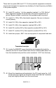
We're almost finished. All we need to do now is install a few remaining parts that have to be handmade - for that "old-world craftsmanship" touch! We'll prepare all those parts now for further assembly. We give you plenty of enameled wire, but if you mess up, you can get a whole 50' spool of it from Radio Shack. 41. Winding L1 and L3 toroid RF coils (two identical units ): Locate 2 of the donut shaped yellow toroid cores provided in the kit.
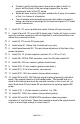
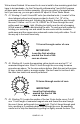
amount of wire cut for this task is the proper amount. If you have too little or too much, then you have not wound the core correctly. Tin each end with solder as before. Tin all the way up to the core body. This winding is the primary of transformer T2. Only 2 turns shown for clarity, 8 turns are needed Each lead is about 1” long 44. Cut off another length of wire, 8 inches long.
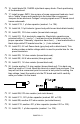
Secondary leads (wound previously) 1 turn with loop then another turn Twist the loop together tightly (not shown tightly for clarity) 47. Locate the smaller transformer (T2) and install it snugly on the PC board. 48. Install the larger transformer (T1) into the indicated location on the PC board. 49. Install L1, a 15 turn toroid inductor wound previously. If desired, a small dab of hot melt glue, bathtub sealer, or caulk may be used to secure the toroids. 50.
3. Connect a dummy load to J1, the amplifier RF output. In a pinch, a light bulb may be used - see the section, "Verifying RF Power Output." 4. Temporarily install a jumper from the collector of Q3 to ground. 5. Apply power to the amplifier but do not turn on the transmitter. Measure the current drawn by the amplifier and slowly rotate the bias pot, R4, clockwise until you reach a reading of ¼ amp. Do not allow the current to rise above ½ amp.
VERIFYING TRANSMITTER RF OUTPUT The most important thing to know is whether your transmitter is delivering some measurable and reassuring level of RF power. Then you can continue on to adding the QRP amplifier and checking out the whole set-up. Ideally, you have a small RF wattmeter, already inserted in the antenna line, capable of accurately measuring low output power in watts. And it cost you less than what you paid for the transmitter kit. Right? In the words of Wayne from "Wayne's World"...
Amateur radio magazines and handbooks provide a variety of circuits for RF wattmeters and relative field-strength indicators, including methods of using your VOM as an indicating device. CQ magazine for March 1990 offers an article by KB4ZGC on how to make a highly accurate yet inexpensive dummy load and wattmeter capable of showing 1/10-watt differences in RF power.
If you hear an AC hum on the transmitted signal, usual causes are RF getting back into the power supply or a bad VSWR on the antenna. These short checks in no way detail any and all problems that can rear their ugly head, but should get you on the way to solving most errors. We'd like to be able to foresee a problem a builder may encounter, but the sheer number of parts and the permutations and combinations of installing them makes any list of precise, exact solutions impossible.
While we believe that the Ramsey enclosure and knob option is a fine value for finishing off your Ramsey kit, we are happy to give you a couple of additional suggestions and our reasons for them. If your first goal is economy and rugged portability, you will find that the circuit board can be mounted nicely in a standard VHS videotape storage box, which also gives room for storing cables, a small homemade keyer, etc. The controls are easily mounted at one end of such a box.
QAMP-30 • 18
The Ramsey Kit Warranty Amateur radio magazines and handbooks provide a variety of circuits for RF wattmeters relativeBEFORE field-strength indicators, including methods of using Please readand carefully calling or writing in about your kit. Most your VOM as indicating device. CQ magazine forfactory. March 1990 offers an problems cananbe solved without contacting the article by Notice that this is not a "fine print" warranty.
QAMP30 20 WATT LINEAR AMPLIFIER Quick Reference Page Guide Introduction to the QAMP-30 ..........4 How it works ...................................4 Parts list ..........................................5 QAMP-30 assembly instructions.....6 Initial testing ..... ............................12 Verifying RF output power ............13 Using the QAMP-30 ......................16 Parts layout diagram .....................17 Schematic diagram .......................18 Ramsey kit warranty .....................