USER GUIDE JANUARY, 2005 V1.20.18 COM3010 SERVICE MONITOR Copyright Ramsey Electronics, Inc.
TABLE OF CONTENTS 1.00 Introduction .....................................................................................................................5 1.01 Opening the Box.......................................................................................................6 1.01.01 Checking Contents......................................................................................6 1.01.02 Plugging in the Battery ..............................................................................6 1.01.
TABLE OF CONTENTS 3.00 Typical Test Procedures............................................................................................ 32 3.10 Transmitter Tests 3.10.01 Transmit Power, Frequency, and Modulation Measurement............. 34 3.10.02 Power Measurements .................................................................................... 36 3.10.03 Frequency Counter Off-Air............................................................................ 38 3.10.
TABLE OF CONTENTS 6.50.07 Various Mode Options............................................................................ 92 7.00 Appendix APPENDIX A: APPENDIX B: APPENDIX C: APPENDIX D: APPENDIX E: Button Reference Chart....................................................................... 94 CTS Tone Frequency List ..................................................................... 96 DCS Code List.........................................................................................
1.
INTRODUCTION 1.01 Opening the Box 1.01.01 Checking Contents Included with the COM3010 Service Monitor: 1 1 1 1 AC Power cord Pretested 3 foot BNC to BNC Cable BNC Whip Antenna Operator’s Manual 1.01.02 Plugging in the Battery Before powering up the COM3010 the battery pack should be plugged into the unit so that it can charge. The battery has been placed in the battery slot for shipment. 1. Remove the rear panel Battery Compartment cover by unscrewing the two thumbscrews. 2. Take the 2.
INTRODUCTION Adding Batteries All three batteries are internally connected in parallel. If you are adding another battery pack to an existing unit, discharge the already installed batteries fully by leaving the COM3010 on until it powers itself off. Only then it is safe to add the new battery pack. Otherwise the new battery arrival may be charged at too fast a rate by the battery already installed and possible damage to the battery could occur.
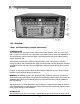
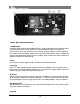
INTRODUCTION H A I B C G D F E 1.02 Overview 1.02.01 Front Panel Inputs, Outputs, and Controls A. RECEIVE IN Jack The RECEIVE IN jack is used to receive signals using a whip antenna, cable, or a probe. Typically a x1 probe is used since a x10 attenuator is not matched for 50 ohms. The RECEIVE IN is also the frequency counter input; this input is split between the receiver and the frequency counter inside the unit. The frequency counter starts counting at approximately 10mV.
INTRODUCTION and tone generation of the COM3010 is desired. This input can be set to a wide range of signal levels as the built-in AGC will change the gain to get a very specific level before modulating the RF out. This input range should be kept between 50mV pk/pk to 5V pk/pk. When you are using this feature, and the EXT modulation is switched on, there are three different AGC modes you should be aware of. These are indicated as an icon next to the MOD IN level field on the left-hand display.
INTRODUCTION J K L T S M N O P R 1.02.02 Rear Panel Connections J. -30dB Output The power meter portion of the COM3010 uses a 100W 30dB attenuator to dissipate power on the heatsink on the back of the unit. The 30dB attenuated output is provided as a convenience to allow safe connection of an external spectrum analyzer or other equipment. For example if you transmitted 100W of power into the GEN OUT jack, 100W = +50dBm.
INTRODUCTION Allows unit to be placed upright and rest on the rear panel. R. Battery Input Jacks Receptacles for connecting battery packs. These can also be used to connect an external DC supply. See the BATTERY INFORMATION section for more details. S. Battery Pack Support Rails T. High-power attenuator heat sink The high-power attenuator is located on the back of this heat sink inside of the case. During power meter testing, this will become quite warm.
INTRODUCTION 1.02.03 Field Selection and Entry With one exception the GENERATE and RECEIVE displays are laid out in the same four quadrant format with each field’s (quadrants) access key remaining the same. GENERATE TX Level Modulation Seq/Reg GENERATE screen: Field 1 is accessed through the GENERATE key. Field 2 is accessed through the FM key. Field 3 is accessed through the LEVEL key. Field 4 is accessed through the COUNT key.
2.
BASIC OPERATION 2.01 Generating a Frequency GENERATE TX Level Modulation Seq/Reg The Frequency Range of the Generator is 100 kHz to 1 GHz in 1 Hz steps. To enter a new generator frequency, press the GENERATE key. The “Ft” Icon will flash. Enter the frequency desired by using the numerical keypad. Use either the MHz/-dBm or kHz/mV key to select your desired units. The COM3010 is now generating the frequency you entered. Example: 2.
BASIC OPERATION 2.03 Setting Generator Level GENERATE TX Level Modulation Seq/Reg RF Level can be entered in either the dBm or Volts scale. The Range is 0 dBm (223 mV) to -140 dBm (0.022uV) in 0.1 dB steps. To enter the Level Press the LEVEL key. The “L” Icon will flash. Enter the Level using the keypad, then press your desired units. The COM3010 is now generating your desired level. Example: To cancel an entry, press 2.
BASIC OPERATION 2.05 Muting the Generator GENERATE TX Level Modulation Seq/Reg To mute the generator at any time, press SHIFT then MHz/-dBm or end with any scaling key. This sets the generator level to – 140dBm as well as setting the generator to its lowest possible level.
BASIC OPERATION 2.06 Modulating the Carrier The carrier frequency can be modulated with either amplitude modulation (AM) or frequency modulation (FM). In AM mode it is possible to generate either a single tone or external modulation; DCS and CTS are not enabled in AM modes. The following combinations are possible in FM : No modulation External + CTS Tone Only Tone + CTS External + DCS Two Tone only Tone + DCS Two Tone + CTS External 2.06.
BASIC OPERATION 2.06 Modulating the Carrier (Continued) GENERATE TX Level Modulation Seq/Reg To generate AM tones press the AM key; the FMi icon will be replaced with AM and % modulation will be displayed. To enter a new AM value of 50%, press AM, 5, 0, ENTER/%. The COM3010 will now be generating AM with 50% modulation and a 1 kHz tone.
BASIC OPERATION 2.06.02 Generating Using External MOD IN GENERATE TX Level Modulation Seq/Reg The external modulation mode allows modulation from an external source via the MOD IN jack. The value you enter for deviation or % AM is followed exactly, and is automatically adjusted by the AGC (automatic gain control). Any level from an external generator between 100mV and 2V peak will be compensated with the AGC circuit. Remember there are three types of AGC supported by the COM3010.
BASIC OPERATION 2.06.03 Generating CTS To generate a CTS tone, press CTS. Current parameters are now shown on the display. To enter a new CTS tone you will need to know its frequency, not the tone #. Use the chart at Modulation Seq/Reg the end of the manual for standard CTS tones. This field will accept any selected frequency from 0.1Hz to 999Hz, so non-standard tones may be used. GENERATE TX Level Example: To enter a new CTS frequency of 78.
BASIC OPERATION 2.06.04 Generating DCS GENERATE TX Level Modulation Seq/Reg To activate DCS, press The LED will light indicating it is on. The DCS code field is now active as indicated by the blinking icon. You must enter the DCS code with the UP / DOWN keys. You will be selecting from an internal list stored in the COM3010. To select a code of 53, use the keys to select the code. For inverted digital code, press SHIFT, DCS; press them again to return to normal.
2.06.05 Modulation Steps You may enter a STEP/Increment value for FM deviation or AM modulation in any of the modulation modes. This entry will also be used for all other format’s deviation steps. For FM press SHIFT, FM and enter in a value from 0.1 Hz to 1 kHz followed by Hz/uV.
BASIC OPERATION 2.06.06 Generating Two-Tone Paging Signals The COM3010 can also generate two tone sequential paging signals. Because there are two tones involved, both displays are used with their corresponding function keys. It is important to remember that each of the display fields is controlled by a specific function key. The 2nd tone parameters are displayed in the RECEIVE display, and controlled by the corresponding RECEIVE function keys (RECEIVE FM, RECEIVE AM, METER SELECT, and @COUNT).
BASIC OPERATION 2.06.06 Generating Two-Tone Paging Signals (Continued) GENERATE TX Level RECEIVE Level Meters Modulation Seq/Reg Counter Freq Meters You wish to generate a typical two-tone, tone only paging signal. Tone one is 349.0 Hz, and tone-two is 433.7 Hz. Sets tone one to 349 Hz. Sets tone two to 433.7 Hz. Sets tone deviation level to 3.5 kHz. (Default level is 4 kHz and does not need to be entered if default level is suitable) Sets two-tone, tone only mode (third mode).
BASIC OPERATION 2.07 Receiving a Frequency RECEIVE Level Meters Counter Freq Meters Setting the receive frequency is performed in a similar manner to setting the generator. To receive a frequency, press RECEIVE FM, or RECEIVE AM, followed by the frequency, fol- lowed by KHz /mV or MHz / -dBm. Example, to receive 162.400 MHz FM: You can toggle the receive mode simply by pressing: toggles current frequency to receive the AM component and, toggles to the FM to receive that portion of it.
BASIC OPERATION 2.09 Using the Frequency Counters RECEIVE Level Meters Counter Freq Meters Your COM3010 contains three different RF frequency counters. Each frequency counter has two gate times. The value counted is the signal presented at the RECEIVE IN jack. COM3010 Frequency Counters Counter Icon Mode Gate Receiver IF Counter Receiver IF Counter Counter, 100Hz-70 MHz Counter, 100 Hz-70 MHz Description 0.1s Used to calibrate received transmissions. As sensitive as the receiver. (<5uV).
BASIC OPERATION 2.10 Using the Frequency Meters RECEIVE Level Meters Counter Freq Meters The frequency meters are selected by pressing METER SELECT multiple times. There are meters unique to both RECEIVE AM and RECEIVE FM modes. Any of these meters may be zoomed for a larger display for easy viewing. To zoom a display, press SHIFT, . Function keys.
BASIC OPERATION COM3010 Meter Displays (Continued) Common Meter Displays Frequency Error Bargraph Scale = 1, Error Positive Frequency Error Bargraph Scale = 2, Error Negative Digital Frequency Error Meter Audio Frequency Meter Description 2.10.06 The frequency error bargraph allows visual calibration of a frequency reference to the internal reference of the COM3010. This is scale-1, error positive. For a more precise error value see the Digital Frequency Error meter below. 2.10.
BASIC OPERATION 2.11 Using the Level Meters Level meters in the COM3010 are accessed by pressing SHIFT, METER SELECT multiple times to cycle through the available meters. Level meters available include RSSI Bargraph, RSSI Counter Freq Meters Digital Meter, Power Meter, Battery Meter, and Serial Status. Each of the meters will be displayed in the Receive/Level Meter display. RECEIVE Level Meters Example: to cycle through the available meters shown below.
BASIC OPERATION 2.12 Zooming the Frequency Meters Each Frequency meter has a corresponding display in the Zoom Meter Mode. The only exception is the +/-4 kHz Deviation Bargraph Meter. The +/-6 kHz Deviation Bargraph Meter is displayed twice in the Zoom Meter Mode list. To Zoom the display, press METER SELECT, then SHIFT, . . Once zoomed, you can continue to press METER SELECT to select other meters, or use the power meter by pressing SHIFT, 3.
BASIC OPERATION 2.12 Zooming the Frequency Meters (Continued) GENERATE TX Level RECEIVE Level Meters Modulation Seq/Reg Counter Freq Meters Example of the text version of the frequency error meter. It gives quick, accurate readings, but may be difficult to visualize while manually tuning an oscillator. Use the frequency error bargraph for tuning.
Your Notes: 32
3.
TYPICAL TEST PROCEDURES 3.00 Typical Test Procedures This section outlines typical measurements that can be made with the COM3010. These test procedures are basic ones designed to help you get familiar with the unit. Once familiar with the COM3010 you will be able to combine and modify these procedures to fit your own operation, increasing its efficiency. This section also assumes the user has a basic understanding of the operation of the COM3010 Service Monitor.
TYPICAL TEST PROCEDURES 3.10 Transmitter Tests 3.10.01 Transmitter Power, Frequency, and Modulation Measurement This procedure allows the technical service professional the ability to measure the Transmitter Frequency Accuracy, RF Power, and FM Deviation or Percent of AM modulation. Frequency Error, FM Deviation, and AM Percent of Modulation can all be measured in both an analog or digital format. The Power measured can be displayed in Watts or dBm. 1.
TYPICAL TEST PROCEDURES Frequency Error Measurement 7. The COM3010 will also display the Counted Frequency (Lower left field) and The Frequency Error (lower right field) in the RECEIVE screen. 8. Press 9. Adjust the transmitter’s frequency until the error displayed is zeroed to the center mark of the Frequency Error Bargraph Meter or the Digital Frequency Error Meter reads zero. to Zoom the Frequency Error meter to the entire RECEIVE screen. Deviation Measurement 10.
TYPICAL TEST PROCEDURES 3.10.02 Power Measurements As with many power meters, the frequency to be measured must be specified for accurate power meter readings. 1. Connect the radio to the RF OUT jack. 2. Transmitter frequency can be entered into the COM3010 using one of two methods: Manually using the IF Counter Method or automatically using the RF Counter Method. IF Counter Method: 3.
TYPICAL TEST PROCEDURES 3.10.02 Power Measurements (Continued) 6. Key the radio into the COM3010; the frequency counter will begin to count the RF signal. The text to the right of the power meter will show “POWER GOOD” to indicate that the count value and calibration are correct. 7. If the counter is not registering you will see “POWER UNCAL”. To remedy this, either use the COUNT IF method or make sure the radio is keyed long enough for the frequency counter to register a valid count. 8.
TYPICAL TEST PROCEDURES 3.10.03 Frequency Counter Off-Air This test allows the user to count the frequency of a transmitter off-air. This is especially useful for identifying the frequency of unmarked radios. 1. Connect the whip antenna to the COM3010’s RECEIVE IN jack. 2. Turn off all FM modulation modes by pressing 3. Press COUNTER multiple times to select RFL, RFL, RFH or RFH, depending on frequency band and gate time desired. See “2.09 Using the Frequency Counters” for more information.) 4.
TYPICAL TEST PROCEDURES 3.10.05 CTS Tone Frequency and Deviation Measurement The COM3010 can accurately measure the frequency and deviation level of CTS sub-audible tones. CTS tones are typically sent at ±0.75 kHz deviation while voice deviation is normally set at ±5 kHz. Therefore it is important to mute the microphone or any other audio input while measuring CTS frequency and deviation. CTS Tone Measurement 1.
TYPICAL TEST PROCEDURES 3.20 Receiver Tests 3.20.01 Receiver Sensitivity and Centering Frequency This procedure will give the technician a general indication of receive sensitivity and frequency accuracy. For more precise sensitivity measurements see “3.20.02 SINAD Measurements”. Receiver Sensitivity 1. Connect a test cable between the COM3010 RF OUT jack and the receiver to be tested. 2. Set the receiver to be tested to the desired test frequency. See the receiver’s owners manual. Example 464.550 MHz.
TYPICAL TEST PROCEDURES 3.20.02 SINAD Measurements This test allows the user to accurately measure the sensitivity of a receiver with a built-in SINAD Test Set. The SINAD meter is accessed using the SHIFT, 8 buttons. The following is a step-by-step SINAD test procedure for testing the sensitivity of a radio. 1. Connect the radio’s antenna to the RF OUT jack. 2. Connect the audio out of the radio to the MOD IN of the COM3010. 3.
TYPICAL TEST PROCEDURES 3.20.02 SINAD Measurements (Continued) 9. The icon displayed on the RECEIVE screen indicates the audio level from the receiver. This icon will indicate if the level is too high (straight up arrow), too low (straight down arrow), adjusting (angled arrow), or correct (flat line). When the level is correct, the SINAD measurement is accurate. Adjust the receiver’s volume control for a flat line.
TYPICAL TEST PROCEDURES 3.20.03 Opening Receiver Squelch Using CTS The following procedure allows the technician to open a receiver’s CTS encoded squelch. The Service Monitor uses “sub-audible” tones, usually under 300Hz at ±0.5 kHz of deviation. 1. Connect a test cable between the COM3010’s RF OUT jack and the receiver under test’s antenna jack. 2. Set the RF Level equal to the receiver’s sensitivity: see receiver owner’s manual. Example: 0.25 uV. 3.
TYPICAL TEST PROCEDURES 3.02.04 Opening Receiver Squelch Using DCS Opening a receivers DCS encoded squelch can be achieved by using the following procedure. The COM3010 supports all the commonly used codes, both non-inverted (N) and inverted (I). 1. Connect a test cable between the COM3010’s RF OUT jack and the receiver under test’s antenna jack. 2. Set the RF Level equal to the receiver’s sensitivity: see receiver owner’s manual. Example: 0.25 uV. 3.
TYPICAL TEST PROCEDURES 3.20.05 Two-Tone Paging This function allows the COM3010 user to open the squelch of a receiver using the Two-Tone Paging format. 1. Connect a whip antenna on the generator RF OUT of the COM3010. 2. Set Generate frequency. Example 3. Enter desired RF Level. Example: 4 V Press 4. Press 5. Use the 6. Set Tone One, Example: 378.6 Hz 7. Use the 8. Set Tone Two, Example: 445.7 Hz Press 9. The deviation is set to a default of 4 kHz.
TYPICAL TEST PROCEDURES 3.20.06 Sending External Modulation The COM3010 has several AGC modes available for different signaling methods. The MOD IN jack is DC coupled to allow proper transmission of digital data as well as accurate reproduction of 4-level paging formats such as FLEX. The COM3010’s AGC circuit takes whatever signal is seen on the MOD IN jack and amplifies it to a specific value to produce the proper modulation output. Voice (Random, Audio Symbol) 1.
TYPICAL TEST PROCEDURES Tone (sine wave symbol) Tone AGC was designed for continuous tones. Once the AGC has set the gain the AGC circuit will verify the output level and correct if necessary, approximately every two seconds. 1. Connect an audio generator such as the Ramsey SG560 to the MOD IN jack. Set the audio generator’s level to approximately 1 Vpp. (50 mVpp to 5 Vpp acceptable). 2. Set the generator for desired RF frequency. Example: 464.15 MHz, Press 3. Turn on external deviation by pressing 4.
TYPICAL TEST PROCEDURES Digital (square wave symbol) Digital AGC helps to get the desired deviation, and it is DC biased. This means that for an input signal of 0-5V, the deviation will only go to the plus side of zero. If the input signal is –2.5V to +2.5V, it will be centered around zero. Also if a 4-level digital signal is used the step size will be an accurately scaled modulation change in relation to the peak voltage of the generator. 1.
TYPICAL TEST PROCEDURES 3.20.07 Testing Repeater Receiver Desensitization Repeaters operate commonly in 2 bands usually at UHF 450 – 470 MHz and 800 MHz. They are occasionally found in the 150-160 MHz VHF bands as well. The COM3010, with its high stability accurate signal source using a calibrated isolator T connector allows you to accurately and quickly verify correct duplexer operation. It is also very easy to check Receiver Desensitization or what’s often referred to as Receiver Desens.
TYPICAL TEST PROCEDURES STEP-1 CALIBRATING AN ISOLATION TEE (ISO-T) 1. You must calibrate the Iso-T to 40dB first in order to insure sufficient isolation and to accurately measure the receiver sensitivity. 2. The COM3010 is set up to generate at the repeater receiver frequency. 3. Attach cables, 50 ohm load and Iso-T as shown in Figure-1 below. 4. Set the generator to -60 dBm 5.
12. TYPICAL TEST PROCEDURES While keyed adjust the generator output as necessary to achieve 12 db SINAD. 13. Subtract the transmitter turned off SINAD from the transmitter turned on SINAD setting to arrive at the actual dB level of desensitization. 14. Typical readings are usually no more than 1 – 3 dB of measurable desensitization.
TYPICAL TEST PROCEDURES 3.20.08 Tuning a duplexer The three types of duplexers commonly used in VHF, UHF and 800 MHz communication systems are: 1. Band Pass 2. Band Pass-Band Reject 3. Band Reject The COM 3010, with its high stability accurate signal source and the associated RSSI receiver, makes accurate duplexer testing and retuning fast and easy. This tuning procedure deals specifically with the Band Reject type, square or round cavity design.
TYPICAL TEST PROCEDURES Set up the COM 3010 to generate and monitor the same frequency. The COM 3010 can be linked for either the transmitter or receiver frequency. STEP-1 TUNING THE RECEIVER SIDE OF THE DUPLEXER (RX PASS) 1. The receive side of the duplexer is tuned to reject the transmitter noise at the transmit frequency. 2. Connect RF OUT to the duplexer antenna port as shown in FIGURE-1 below. This is done in order to inject each signal for the test. -50 dbm output is a good starting point.
TYPICAL TEST PROCEDURES STEP-2 TUNING THE TRANSMITTER SIDE OF THE DUPLEXER (TX PASS) 1. The transmit side of the duplexer is tuned to reject noise at the receiver frequency. 2. Set up the COM 3010 to generate and monitor the repeater receiver frequency. 3. Attach the 50 Ohm load directly to the duplexer receiver port as shown in Figure-2. 4. Connect RF OUT to the duplexer antenna port as shown. This is done in order to inject each signal for the test. -50dbm output is a good starting point. 5.
TYPICAL TEST PROCEDURES STEP-3 INSERTION LOSS FINAL TEST 1. Leave the RF OUT cable connected to the duplexer antenna port. You can final test the duplexer to make sure that it is operating correctly by an insertion loss test. 2. While the RECEIVE IN is connected to the transmitter side of the duplexer, switch the generator to the repeater transmit frequency. Make sure the 50 Ohm load is connected to the repeater receiver port. 3.
4.
ADVANCED FEATURES 4.10 Memories The time will probably come when you will want to store settings for repetitive testing of equipment. The COM3010 memory is broken down into Sequences that contain Registers. A Sequence can be assigned to each different piece of equipment you test. The registers in that sequence can contain all the test set-ups needed for that specific piece of equipment. A register will store most items on the display except for sweep setups.
ADVANCED FEATURES Memories (Continued) Recalling Registers 1. Press 2. Enter the two digit number of the sequence you desire. Example: 02 3. Use the Up/ Down arrows to scroll through different sequences 4. Press Enter the two digit register number or Use the Up/Down arrows to scroll through different registers. or Copying Registers 1. Recall the sequence and register to be moved, then the sequence and register to be copied to. Example: Sequence 5, register 13 copied to sequence 7, register 13.
ADVANCED FEATURES Memories (Continued) Deleting Entire Sequences 1. Press 2. Enter Sequence Number. Example: Sequence 2 3. Press 4. Press to enter Delete mode. to select ‘yes’. Default Sequence and Register Sequence 99 Register 99 is reserved for power-up settings. This replaces the default start-up setting when the unit is powered on. If a new power-up setting is desired, set the Generate and Receive screens as required and save your new power-up default as normal using SEQ 99 REG 99.
ADVANCED FEATURES 4.20 Smart Link Smart link allows the Receiver and Generator to be linked together. If the Generator and Receiver are on the same frequency they will change to the same frequency if a new one is entered in either the Generate or Receive screen. If the Generate and Receive Frequencies are different the spacing between them will remain the same when a new frequency is entered.
ADVANCED FEATURES 4.30 Scanner The scanner function is used to monitor known frequencies for proper operation. The scanner function will allow sweeping through any sequence of memories that are preprogrammed into the COM3010. This allows scanning of up to100 channels in a single sweep. The more channels stored, the longer the scan times. When setting up scan channels choose an open sequence. We recommend using a memory location in the range from 80-98 to store scanner sweeps.
ADVANCED FEATURES 4.30 Scanner (Continued) 11. Press 12. Enter sequence number 13. Press 14. Press SHIFT, 7 to enter the scanner mode. 15. Enter the sequence number 16. Press 17. Turn the squelch knob until the squelch just closes. Press scan approximately 5 seconds after the squelch closes. and the information is stored in the “02” register. The unit will start to It is also possible to adjust the squelch to trigger and stop the sweep at a given RSSI level.
ADVANCED FEATURES GENERATE TX Level RECEIVE Level Meters Modulation Seq/Reg Counter Freq Meters 4.40 Sweep Generator The sweep generator is used for testing frequency response of filters, flatness of cables, and similar tests. This function can be used in conjunction with a spectrum analyzer or the selfcalibrated RSSI meter on the COM3010 with the LINK activated. On the GENERATE screen: The FB Field represents the Frequency at which the sweep begins. It is accessed through the GENERATE key.
ADVANCED FEATURES 4.40 Sweep Generator (Continued) The START field is accessed with the METER SELECT key. The EXIT field is accessed with the @COUNT key. To set up a sweep from 10 MHz to 1GHz (1000 MHz) with a level of –120dBm, linear, with 100 steps, follow these keystrokes: 1. To enter the sweep function, press SHIFT,1. 2. Enter 10 MHz in the BE field. 3. Enter 1000 MHz in the FB field. 4. Set LEVEL to –120 dBm. 5. Set TYPE to linear. 6. Set the number of points to 100 in the NUM field. 7.
ADVANCED FEATURES GENERATE TX Level RECEIVE Level Meters Modulation Seq/Reg Counter Freq Meters 4.50 User Options: The user options for the COM3010 are available by pressing SHIFT, 6. This brings you to the Main Options Menu. This menu is displayed on both the GENERATE and RECEIVE Screens. The options listed that are available to the user are in brackets. The options between the ‘<‘ ‘>‘ signs are password protected and only available to qualified COM3010 service technicians.
ADVANCED FEATURES GENERATE TX Level RECEIVE Level Meters Modulation Seq/Reg Counter Freq Meters General Options: These are accessed by pressing SHIFT, 6, then the GENERATE key. On the GENERATE screen: The Buzzer is toggled on and off using the key and turns all buzzer events on or off. Cable Comp: adds 1 dB to the power reading at 1 GHz, linearly declining to 0 dB of added power at 0 Hz. Use the button to toggle this feature on and off.
ADVANCED FEATURES General Options (Continued) On the RECEIVE screen: The Dim function allows the user to use the UP/DOWN arrows to select the display intensity. Access this option using the button. [Exit&Save] exits this menu and saves all option settings using the key. Splash allows disabling of the start up splash screen and is toggled using the key. The Flt Cnt (Counter Filter) function allows disabling of the frequency counter filter. Press the key to toggle this function.
ADVANCED FEATURES Clear Memories: Clear Memories is an option that allows you to clear all registers and sequences including the special 99.99 registers. This allows you to “clean up” the COM3010 if planning on setting it up for a new test bench or other purpose. To get to the Clear Mems function, press The button selects [YES] to delete all memory locations or the [NO] and exits to the Main Options Menu. button selects 4.60 Battery Power Saver This function will blank both the displays.
Your Notes: 70
5.
USER CALIBRATIONS RECEIVE Level Meters GENERATE Counter Freq Meters Modulation TX Level Seq/Reg 5.00 USER CALIBRATIONS Several features of the COM3010 can be calibrated by the user: The RSSI Meter, the Master Time Base, and the Modulation Bargraph Meter. When displaying the calibration screens items surrounded by ‘[ ‘]’ indicate user functions, where the ‘<‘ ‘>‘ indicate password functions. Password functions are reserved for technicians with proper equipment only. 5.
USER CALIBRATIONS GENERATE TX Level RECEIVE Level Meters Modulation Seq/Reg Counter Freq Meters 5.20 Calibrate the Master Time Base The COM3010’s Master Time Base is a voltage controlled TCXO with an accuracy of better than 0.1ppm over a given time and temperature. The time base is easily adjusted to any calibrated standard or reference available.
USER CALIBRATIONS 5.20 Calibrate the Master Time Base (Continued) 1. Connect an accurate reference frequency source to the COM3010’s RECEIVE IN jack. 2. Press 3. Press 4. to enter the Main Calibration Menu. to select [Freq Ref]. Note the warning about having a good reference. selects [YES] to continue and enters the Frequency Calibration menu. 5. Press and enter the source frequency. Example: 955 MHz. 6.
USER CALIBRATIONS 5.30 Calibrate the Modulation Meter Occasionally the quadrature detector of the COM3010 may need alignment to center the modulation meters. 1. Connect the RF OUT to the RECEIVER IN using a BNC to BNC cable. 2. Press 3. Press 4. Press to restore to system default of zero or press calibration. 5. Press any key to begin meter calibration. 6.
Your Notes: 76
6.
6.10 Digital Modulation on the COM3010 When connecting the COM3010 an external broad-band modulation analyzer, the analyzer will typically see a larger deviation than expected. It may be as much as 5%. This is due to the very fast frequency changes used to “emulate” FM by digitally switching frequencies in steps. The upper line is the desired modulating waveform at 1 kHz, and the lower line is what is needed digitally to re-create this same signal.
DETAILED INFORMATION 6.20 Advanced Power Meter Information The COM3010 power meter is a voltage mode power meter. The COM3010 power meter is not a true RMS type of power meter, meaning that it will measure your primary carrier voltage accurately and convert it to a power in dBm. It is possible for harmonics and other signals to cause error. Measurement is performed internally using a broadband log detector IC with 70 dB of dynamic range.
DETAILED INFORMATION 6.30 30 dB Rear Panel Attenuator Output. The 30dB attenuator output on the back of the COM3010 can be used for a variety of external hookups such as spectrum analyzers, modulation analyzers, and other test gear. It can also be used to loop back into the receiver input on the front to obtain good frequency counts during power testing. The Receiver Input on the COM3010 is a sensitive circuit which is sent not only to the Receiver, but also the Frequency Counters.
DETAILED INFORMATION 6.40 Advanced SINAD Information What is SINAD? SINAD is a parameter which provides a convenient measurement of the quality of an audio signal from a radio or other communications device. SINAD is a simple measurement of the power ratio between signal + noise + distortion to just noise + distortion. To remove the signal to calculate the SINAD, a narrow band-stop filter is employed. Then an RMS value is found for the unaltered signal, and another RMS value for the filtered signal.
DETAILED INFORMATION bring up any incoming audio level used during test to a point that the sampling circuit can use it to full advantage and best dynamic range. The COM3010 can amplify fairly low level signals up to a usable level so that you don’t add distortion errors to your measurement by turning up the volume of a radio so high that it ruins the SINAD test reading.
DETAILED INFORMATION 6.50 RS232 Communications The serial remote control function of the COM3010 provides all the same operations that can be accessed from the front panel except for the scanner and sweep functions. The serial port on the back of the COM3010 is filtered to prevent RF leakage. This filtering may cause errors at baud rates over 57.6K; therefore, it is best to use 57.6K baud and lower with the COM3010.
3. DETAILED INFORMATION To enter the Options Screen. 4. Selects Serial Options. 5. Use the 6. buttons to select 9600 baud. to exit, save changes, and return to Operational Mode. 7. Press several times until the serial status is displayed on the COM3010. This meter will normally only be used to troubleshoot communications problems. 8. Type “SYS OPEN 555” [ENTER] (No quotes) in the terminal software 9. The COM3010 should respond with “Welcome from unit 555” and give you an access prompt of “>>“.
DETAILED INFORMATION again. Other terminal software should not exhibit this problem. Testing with some legitimate commands: Enter “SYS OPEN 555” [ENTER], and the COM3010 should connect. Enter “SET GF 403.25M” [ENTER]; this will set the generator frequency to 403.25MHz. Enter “SET GL –45dBm” [ENTER]; this will set the level to –45dBm Now that you are finished, type “SYS CLOSE [ENTER]” The COM3010 will reply with “Disconnecting, Bye.” and will not respond until you issue another “SYS OPEN 555” command.
DETAILED INFORMATION 6.50.02 SYS Commands Major SubCommand Command Format Low High Returns Description System Commands ### OK/BAD Opens serial communications with this COM3010 if address matches setting. OK/BAD Closes serial communication. After this, nothing is sent or received. 999.999 OK/BAD Once open, this changes to a new address, and leaves session open.
DETAILED INFORMATION 6.50.03 SET Commands Maj or SubCommand Format Low High Returns Description Generator Side SET GF ###.##### 0.100000M 1000.000000 OK/BAD #MHz Hz MHz SET GEN,GENSTAT ON/OFF ON OFF OK/BAD E Set Generator frequency SET GL,LVL,LEVEL -###.#dBm -120 0 OK/BAD Sets the Generator State. By default when entering the serial mode, this is set to ON.
DETAILED INFORMATION 6.50.03 SET Commands (Continued…) SET GSTEP ###.##### 0.0MHz #MHz 1000.000000 OK/BAD MHz OK/BAD SET GUP SET GDOWN OK/BAD Receiver Side Major SubCom- Command mand Format Low High Returns ###.#### 0.100000 1000.
DETAILED INFORMATION 6.50.04 MEM Commands Major Command Subcommand Format Low High Returns Description Memories OK/BAD Recall Memory from sequence.register NXT OK/BAD Recall next memory in the sequence MEM PREV OK/BAD Recall previous memory in the sequence MEM SAVE ##.## 00.00 99.99 OK/BAD Save memory in specified sequence.register MEM DEL ##.## 00.00 99.99 OK/BAD Delete specified sequence.register MEM GET MEM ##.## 00.00 99.
DETAILED INFORMATION 6.50.05 GET Commands Major Sub-command Comma nd Low High Returns Description Bottom Meters GET RFCOUNT 0 1200.000000M ####.##### Get current RF frequency count specified by the Hz #MHz current counter mode (see counter mode lists) GET AFCOUNT 0 6000 ####.#kHz Get current AF count, only if AF counter is selected as one of the meters GET FMDEV 0 +/-7kHz +#.##kHz/#.##kHz Get current FM deviation (numerically) GET DELTAF GET DBSINAD,SINA 0dB D,SIN 40dB ##.
DETAILED INFORMATION 6.50.05 GET Commands (Continued…) Major SubComma Command nd Operating Values GET GF Low High Returns Description GET 1000.000000M ####.##### Get Generator Frequency Hz #MHz GEN,GENSTATE OFF ON ON/OFF Gets the current state of the generator. GL,LVL,LEVEL -120.0dBm 0dBm ###.
DETAILED INFORMATION 6.50.
DETAILED INFORMATION 6.50.06 Various Meter Mode Options Lower Meter Mode Table Mode # 1 2 3 4 5 6 7 8 9 Upper Meter Mode Table 1 2 3 4 Mode Name Frequency Error Graphic Frequency Error Text FM Modulation Graphic +/-7kHz FM Modulation Graphic +/-4kHz FM Modulation Text AM Percent Graphic AM Percent Text Audio Frequency Counter Sinad Meter RSSI Bargraph RSSI Text RF Power Power Supply State/Voltage Counter Mode Table Mode # Mode Name 1 Direct RF counter, 0-100MHz, 0.
DETAILED INFORMATION 6.50.
7.
APPENDIX APPENDIX A BUTTON REFERENCE CHART: Button Description Shift POWER Turns power on and off. None EXT Toggles external modulation mode and selects deviation. EXT AGC Cycles the various AGC modes for the external input. INT Toggles the internal modulation mode and selects tone. PAGING Accesses the various paging modes that the COM3010 supports (Two Tone) CTS Toggles CTS tone and selects tone. None DCS Toggles DCS mode and selects INVERT DCS code.
APPENDIX Button Description Shift Description 8 Enters an “8” SINAD1K Macro for setting up SINAD testing. 9 Enters a “9” SINAD400 Macro for setting up SINAD testing. 0 Enters a “0” PWR SAVE Turns off the displays to save power. . Enters a “.” ZOOM METER Zooms the current Freq Meter.
APPENDIX APPENDIX B CTS TONE FREQUENCY LIST: Standard EIA CTS Tones (Hz) 67.0 79.7 91.5 103.5 118.8 136.5 156.7 179.9 210.7 241.8 71.9 82.5 94.8 107.2 123.0 141.3 162.2 186.2 218.1 250.3 74.4 85.4 97.4 110.9 127.3 146.2 167.9 192.8 225.7 77.0 88.5 100.0 114.8 131.8 151.4 173.8 203.5 233.
APPENDIX APPENDIX D TWO TONE MODES: Paging Mode Tone 1 length Tone 2 length Wait for squelch delay Tone Only 0.4 Seconds 0.8 Seconds 1.3 Seconds Voice 1 Second 3 Seconds 1.3 Seconds Battery Save 2.7 Seconds 0.8 Seconds 1.3 Seconds Group Call 0 Seconds (Not sent) 8 Seconds 1.3 Seconds APPENDIX E GENERAL OPTIONS TABLE Option Name: Choices Default Description Buzzer ON / OFF ON Turns all buzzer sounds on or off.
COM3010 SPECIFICATIONS Features: Display: 2 Vacuum Fluorescent graphical displays, 16 x 140 pixels Memories: 100 sequences of 100 registers, plus system memories Sweep Features: Linear, octave, and decade of up to 1000 pts for sweeping generator Scanner Mode: Allows scanning through a sequence of 100 stored settings Sinad Meter: Display reading from –30 dB of SINAD to 0 dB.
COM3010 SPECIFICATIONS Receiver: Frequency: 100 kHz to 1.0 GHz Step size: 10 Hz Sensitivity: Less than 2 uV, 1 MHz to 512 MHz; less than 3 uV, 512 MHz to 1 GHz; unspecified, 100 kHz to 1 MHz FM Demod: 0 to 7 kHz, 0 to 4 kHz AM Demod: 0 to100% CTS Decode: In AF frequency count Frequency error: 0 to1 MHz, two methods of bargraph and count AF Demod output: 1 Vp-p for 7 kHz deviation Gates: 0.
Accessories: Battery Pack: BP3010 additional battery pack to extend battery life (1 pack supplied, 3 max) Carrying Case: CC3010 custom Cordura® padded travel case w/ strap 102
Certification Ramsey Electronics, Inc. certifies that this product meets its published specifications at the time of manufacture, and that the calibration measurements are traceable to the United States National Bureau of Standards. Warranty Ramsey Electronics, Inc. warrants this product against defects in materials and workmanship for a period of one year from the original manufacture date. Ramsey Electronics, Inc.
RAMSEY ELECTRONICS, INC. 590 Fishers Station Drive Victor, NY 14564 (585) 924-4560 www.ramseytest.com Copyright Ramsey Electronics, Inc. 2005, All rights reserved COM3010 January 2005 V1.20.