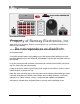
USER GUIDE JANUARY, 2005 Rev. 1.3 Property of Ramsey Electronics, Inc. Do not reproduce or distribute. SG560 SIGNAL GENERATOR Copyright Ramsey Electronics, Inc.
TABLE OF CONTENTS Introduction • Opening the Box..................................................................................................................4 • Quick Start .............................................................................................................................4 • Introduction...........................................................................................................................5 • Front Panel Overview .............................................
Property of Ramsey Electronics, Inc. INTRODUCTION Do not reproduce or distribute.
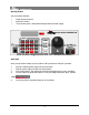
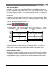
INTRODUCTION Opening the Box Your new SG560 includes: 1 1 1 SG560 Signal Generator Operator’s manual 120/240 VAC Input, 12VDC/500mA Output External Power Supply SG560 AUDIO GENERATOR SHIFT DATA 1 2 3 a b c MHz V FREQ Property of Ramsey Electronics, Inc. POWER 4 5 6 e f kHz mV LEVEL d 7 8 9 Hz OFFSET 0 SHIFT RCL STO SHAPE . 0-5MHZ TRUE-DC (-) (+) Do not reproduce or distribute.
INTRODUCTION Introduction The SG560 is more than an audio generator. It is also a signal generator that produces AC signals with DC coupling at the output jacks like a digital signal generator. The versatility of the SG560 will allow you to recreate many basic signals used in testing situations. The SG560 allows you to generate square waves, sine waves, and triangle waves of any frequency from 0Hz to 5MHz in 0.1MHz steps.
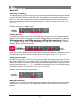
INTRODUCTION A SHIFT C DATA 1 2 3 a b c MHz V FREQ 4 5 6 B e f kHz mV LEVEL d POWER 7 8 9 Hz OFFSET . 0 SHIFT RCL STO SHAP E mute SG560 AUDIO GENERATOR D E 0-5MHZ TRUE-DC (- ) (+) Front Panel Overview Property of Ramsey Electronics, Inc. A: The display area. The first line: F: for frequency, shape as a two-character icon, and a letter to indicate last recalled or saved memory. Do not reproduce or distribute.
Property of Ramsey Electronics, Inc. BASIC USE Do not reproduce or distribute.
BASIC USE Basic Use Generating a Frequency: To enter frequency, press the FREQ key to get into the desired field. A blinking cursor will indicate that the field is selected. Enter the value. For example, for a frequency of 1kHz, press 1, then kHz. The cursor will return to the start of the field and the knob can be used to increment and decrement the field by the preset step size. To abort an entry, press FREQ, LEVEL, or OFFSET. Example: Generate a 2.34MHz signal.
BASIC USE Setting Generator Offset: To enter a DC offset, press the OFFSET key, then any voltage in the range of 0-5V with 10mV of resolution. The offset is a DC component added to the AC signal. With the offset at zero volts the AC component is centered around zero and the average voltage is zero volts. When a DC offset is entered it is added to the waveform, moving the center up (or down) to the level desired. Remember that SHIFT, OFFSET will enter the offset step size.
BASIC USE Saving and Recalling Memories: To save a memory, set up the SG560 into the desired frequency, level, offset and wave shape. Press SHIFT, STO and the memory location a through f. These settings are stored in nonvolatile FLASH memory for recall and will be saved whether or not power is applied to the unit.
Property of Ramsey Electronics, Inc. DETAILED INFORMATION Do not reproduce or distribute.
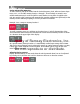
DETAILED INFORMATION Examples of Waveforms and Offsets Example of 2V peak to peak with 0V offset and 0.3V offset. +1.3V +1.0V +0.3V +0.0V -0.7V -1.0V Example of noise test with 0.4V peak to peak and 5V of offset to power a circuit. Property of Ramsey Electronics, Inc. +5.2V +5V • +0.2V +0.0V -0.2V - Do not reproduce or distribute. Example of square wave with 5V peak to peak and 2.5V of offset to recreate a TTL level waveform. +2.5V +5.0V +0.0V +2.5V -2.5V 0.
DETAILED INFORMATION Using the SG560 Differential Outputs Since the SG560 has a differential output, the (+) jack is 180 degrees out of phase with the (-) jack. If the offset is at 5V the (-) jack has -2.5V of offset and the (+) jack has +2.5V in reference to the internal common point. This gives the combined total of 5V between the jacks. If there were 100uV of noise on both the (+) and (-) terminals in reference to the internal reference, it would be common-mode noise and wouldn’t be seen on the jacks.
DETAILED INFORMATION Setting Meter Output Impedance The default output impedance of the SG560 is 50 ohms, but it is possible to change this setting through the use of internal jumpers. The alternate settings are 0 ohms, and 25 ohms output impedance. A 0 ohm impedance simply means that the output of the SG560 would be coming directly from a powerful opamp inside the SG560. With the unit set for 0 ohms output impedance there are no protection resistors between the jacks and the opamp.
DETAILED INFORMATION Signal Descriptions: TP1 is the SG560 direct output; note the flat line vs. frequency. TP2 is the correct filter output as expected of a properly input and output matched filter. TP3 is the frequency response of the lower filter when no matching or an incorrect matching resistor is used while testing the circuit. Note the difference between TP2 and TP3.
DETAILED INFORMATION Dealing with Small Signal Levels and Noise: If small signal levels are needed for a test setup and the output noise of the SG560 is too high, an attenuator on the output of the SG560 will scale the signal level and the noise down to an acceptable level. The output could be limited with a resistor divider circuit as well, but it may be desirable to use a balanced attenuator that will attenuate both the positive and negative outputs equally to keep noise to a minimum.
DETAILED INFORMATION Your Notes: Property of Ramsey Electronics, Inc. Do not reproduce or distribute.
DETAILED INFORMATION Your Notes: Property of Ramsey Electronics, Inc. Do not reproduce or distribute.
Property of Ramsey Electronics, Inc. APPENDIX Do not reproduce or distribute.
APPENDIX Standard EIA CTS Tones (Hz) 67.0 79.7 91.5 103.5 118.8 136.5 156.7 179.9 210.7 241.8 71.9 82.5 94.8 107.2 123.0 141.3 162.2 186.2 218.1 250.3 74.4 85.4 97.4 110.9 127.3 146.2 167.9 192.8 225.7 77.0 88.5 100.0 114.8 131.8 151.4 173.8 203.5 233.6 Property of Ramsey Electronics, Inc. Do not reproduce or distribute.
APPENDIX Property of Ramsey Electronics, Inc. Do not reproduce or distribute.
SPECIFICATIONS Features: •Display: 2x16 Character Display •Memories: 6 Nonvolatile Locations •Displays: Frequency, Waveshape, Peak to Peak Voltage, Offset Voltage, Memory Selected •Power Input: 12-16VDC, 500mA, 3.5mm plug •Waveforms: Sine, Square, Triangle •Functions: Mute, Customized steps Generate: •Frequency: 0.0Hz to 5MHz Sinewave; 0.0Hz to 1MHz Square and Triangle waveforms •Frequency Steps: 0.1Hz •Frequency Accuracy: ±15ppm standard Property ofpeakRamsey •Output Level: 0V-10V to peak, 0.
Certification Ramsey Electronics, Inc. certifies that this product meets its published specifications at the time of manufacture, and that the calibration measurements are traceable to the United States National Bureau of Standards. Warranty Ramsey Electronics, Inc. warrants this product against defects in materials and workmanship for a period of one year from the original manufacture date. Ramsey Electronics, Inc.
Property of Ramsey Electronics, Inc. Do not reproduce or distribute. RAMSEY ELECTRONICS, INC. 590 Fishers Station Drive Victor, NY 14564 (585) 924-4560 www.ramseytest.com Copyright Ramsey Electronics, Inc. 2005, All rights reserved 24 SG560 January 2005 Rev. 1.