STEREO HEADPHONE AMPLIFIER Ramsey Electronics Model No. SHA1 Need a way to listen to line level audio from a tape deck or CD player? Need a way of boosting up any low level signal to earphone level for top quality stereo listening? This kit has CD quality audio capabilities with super low distortion, a wide frequency spectrum, and a superior signal to noise ratio! • Uses the LM386 audio amplifier ICs. • Better than 100dB Signal to noise ratio.
RAMSEY TRANSMITTER KITS • FM100B Professional FM Stereo Transmitter • FM25B Synthesized Stereo FM Transmitter • MR6 Model Rocket Tracking Transmitter • TV6 Television Transmitter RAMSEY RECEIVER KITS • FR1 FM Broadcast Receiver • AR1 Aircraft Band Receiver • SR2 Shortwave Receiver • SC1 Shortwave Converter RAMSEY HOBBY KITS • SG7 Personal Speed Radar • SS70A Speech Scrambler • BS1 “Bullshooter” Digital Voice Storage Unit • AVS10 Automatic Sequential Video Switcher • WCT20 Cable Wizard Cable Tracer • LC1 Ind
Ramsey Publication No. MSHA1 Price $5.00 KIT ASSEMBLY AND INSTRUCTION MANUAL FOR STEREO HEADPHONE AMPLIFIER KIT How does it work .................... Assembly Strategy ................. Parts List ................................ Parts Layout Diagram ............ Part Values Diagram .............. Schematic .............................. Assembly Steps ..................... Testing the SHA1 ................... Troubleshooting ..................... 4 6 7 8 9 10 12 16 17 RAMSEY ELECTRONICS, INC.
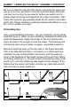
What is it and how does it work? Let’s take a look at the schematic diagram, and we will follow through from input to output to get a general idea how this kit works, and why. We will look only at the left channel circuitry starting at J1 since the right channel is identical to the left. A line level audio signal is placed in J1. Line level means an audio signal of around 1V peak to peak, and will give a reading of 0dB on a VU meter. The audio passes through C1, a coupling capacitor.
C3 is another coupling capacitor, and it serves the same purpose as C1 at the start of the circuit. This prevents the DC portion of the signal on the output of U1 from being sent to the earphones. VR1, C15 and C16 supply the regulated DC voltage for the circuit.
RAMSEY “LEARN-AS-YOU-BUILD” ASSEMBLY STRATEGY Be sure to read through all of the steps, and check the boxes as you go to be sure you didn't miss any important steps. Although you may be in a hurry to see results, before you switch on the power check all wiring and capacitors for proper orientation. Also check the board for any possible solder shorts, and/or cold solder joints.
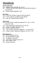
SHA1 PARTS LIST Semiconductors 2 LM386 Audio Amplifier ICs (U1,2) 1 1N4002 rectifier diode (Black body with white stripe on one end) (D1) 1 7808 Voltage Regulator (U3) Resistors 2 4.7K ohm resistors (yellow-violet-red) (R2,7) 2 2 ohm resistors (red-black-gold) (R4,8) 2 10K ohm potentiometers (R3,6) Capacitors 5 .01uF ceramic capacitors (Marked .01, 10n, or 103) (C4,8,10,12,14) 4 10uF electrolytic capacitors (C1,6,15,16) 1 470uF to 1000uF capacitor (C2) 2 220uF capacitors (C3,7) 2 .
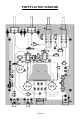
PARTS LAYOUT DIAGRAM SHA1 • 8
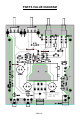
PARTS VALUE DIAGRAM SHA1• 9
SHA1 • 10
SHA1• 11
ASSEMBLING THE SHA1 HEADPHONE AMPLIFIERS: Sort out all of your parts to begin with, making sure you have all of the parts required. You can use old egg cartons to hold various parts to make them easier to find. Make sure to mount parts on the correct side! You will want to use the parts layout diagram to assist you in finding where the parts go. 1. Orient the board in the same direction as the parts layout diagram. 2. Install C12, a .01uF ceramic capacitor (Marked .01, 10n, or 103) 3.
11. Install U2, one of the LM386 audio power amplifier ICs. Check the orientation of this chip to make sure the dot or notch representing pin one is in the same direction as shown in the parts diagram. Make sure all eight pins are through the board before soldering. Note that it is very easy to have a pin folded under the IC instead of being though the holes. This problem is easy to remedy before you solder the IC. 12. Install R8, a 2 ohm resistor (red-black-gold). 13. Install C9, one of the .
usually indicating the negative (-) terminal of the component. You will notice on the parts layout diagram that the hole for the positive terminal is denoted, not the negative one. You will want to install this component with the positive (+) lead in the same orientation as shown in the parts layout diagram. If you do not install it correctly, you will end up with all sorts of problems in the circuit. 23. Install C3, a 220uF electrolytic capacitor.
35. Install C16, 10uF electrolytic capacitor. Watch polarity! 36. Install U3, the 7808 voltage regulator. You will want to bend the center lead out and orient the part so that the writing on the front of the part faces the outside of the board. Solder all three leads. 37. Install C15, the last 10uF electrolytic capacitor. Again, be sure to orient the cap as the silkscreen shows. 38.
TESTING THE SHA1 You will need the following equipment for this test. Audio source such as signal generator, CD player, or tape deck. RCA jacks to feed audio to the SHA1 Good quality headphones. A 9 volt battery or DC power supply Simply connect your SHA1 up as if you were going to use it. 1. Connect your signal source to the two RCA jacks on the SHA1. 2. Hook up the 9V battery or power supply. 3. Turn the volume controls all the way counter clockwise. 4. Plug in your earphones. 5.
TROUBLESHOOTING TIPS PROBLEM: No sound out of any channel. SOLUTION: Use a DMM to check the power supply voltage, do you have a fresh battery? If everything is OK, check your assembly, especially your parts orientation (D1?). Also check your earphones for proper operation as well as your sound source. PROBLEM: One channel is out, the other works OK. SOLUTION: You may have a short or open somewhere through the circuit. This is where an oscilloscope would come in handy.
SHA1 • 18
The Ramsey Kit Warranty Please read carefully BEFORE calling or writing in about your kit. Most problems can be solved without contacting the factory. Notice that this is not a "fine print" warranty. We want you to understand your rights and ours too! All Ramsey kits will work if assembled properly. The very fact that your kit includes this new manual is your assurance that a team of knowledgeable people have field-tested several "copies" of this kit straight from the Ramsey Inventory.
SHA1 STEREO HEADPHONE AMPLIFIER KIT Quick Reference Page Guide How does it work .............................. Assembly Strategy............................ Parts List........................................... Parts Layout Diagram ....................... Part Values Diagram ........................ Schematic ......................................... Assembly Steps ................................ Testing the SHA1 ............................. Troubleshooting ................................