BINARY 4 to 16 LINE DECODER Ramsey Electronics Model No. B D 1 2 4 8 4 1 6 0 1 2 3 4 5 6 7 8 9 10 11 12 13 14 15 BD416 The BD416 provides a simple 4 line BCD (Binary-Coded-Decimal) to one of 16 line output decoder. This is useful if you need to control up to 16 devices and only have 4 lines available. The outputs can control a 5 volt DC device @ up to 20mA. Input levels are 5 volt active high logic levels.
PARTIAL LIST OF AVAILABLE KITS: RAMSEY TRANSMITTER KITS • FM10C, FM25B FM Stereo Transmitters • AM1C, AM25 Transmitter RAMSEY RECEIVER KITS • FR1C FM Broadcast Receiver • AR1C Aircraft Band Receiver • AR2 Aircraft Band Receiver • SR2C Shortwave Receiver • AA7C Active Antenna • SC1C Shortwave Converter RAMSEY HOBBY KITS • SG7 Personal Speed Radar • SS70C Speech Scrambler/Descrambler • TT1CTelephone Recorder • MD3C Microwave Motion Detector • PH14C/15C/16C Peak hold Meters RAMSEY AUDIO KITS • SHA1C and SHA2 H
Ramsey Publication No. BD416 Manual Price Only $5.00 INSTRUCTION MANUAL FOR BINARY 4 to 16 LINE DECODER TABLE OF CONTENTS Introduction/Circuit Description....................... 2 Parts Layout Diagram ..................................... 7 Schematic ....................................................... 8 “Learn-As-You-Build” Kit Assembly .............. 10 Parts List ....................................................... 11 Assembly Steps ............................................ 12 Conclusion .....
Introduction The BD416 is a simple 4 line binary input to one of 16 lines output interface. The output can be configured to latch the output when a valid data signal is applied. The valid data signal may be either an active high or active low logic level input. In the latched output configuration the output may be set to initialize to a set, output line “0” low, or reset, output line “15” low, state at power-up.
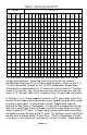
TABLE 1: BD416 INPUT/OUTPUT INPUT B B B B 3 2 1 0 0 0 0 0 0 OUTPUT 1 2 3 4 5 6 7 8 9 1 0 1 1 1 1 1 1 1 1 1 1 1 1 1 1 2 1 1 3 1 1 4 1 1 5 1 0 0 0 1 1 0 1 1 1 1 1 1 1 1 1 1 1 1 1 1 0 0 1 0 1 1 0 1 1 1 1 1 1 1 1 1 1 1 1 1 0 0 1 1 1 1 1 0 1 1 1 1 1 1 1 1 1 1 1 1 0 1 0 0 1 1 1 1 0 1 1 1 1 1 1 1 1 1 1 1 0 1 0 1 1 1 1 1 1 0 1 1 1 1 1 1 1 1 1 1 0 1 1 0 1 1 1 1 1 1 0 1 1 1 1 1 1 1 1 1 0 1 1 1 1 1 1 1 1 1 1 0 1 1 1 1 1 1 1 1 1 0 0
are always in opposite states. Our flip-flops also have set and reset controls. When the set control is pulsed low and returned to a high level the “Q” output is set to a high level. If reset is pulsed low and returned high the “Q” output is set to a low level. We’ll talk more about these signals later. The same inputs, B0 thru B3, are connected to the “D inputs, pins 2 and 12 of U1 and U5, of the 4 “D” flip-flops.
PARTS LAYOUT DIAGRAM BD416 • 7
RAMSEY “LEARN-AS-YOU-BUILD” ASSEMBLY STRATEGY Be sure to read through all of the steps, and check the boxes as you go to be sure you didn't miss any important steps. Although you may be in a hurry to see results, before you switch on the power check all wiring and capacitors for proper orientation. Also check the board for any possible solder shorts, and/or cold solder joints.
PARTS LIST Resistors 4-10K ohm (brown-black-orange), R1, R2, R3, R4 Capacitors 2-10uF C6, C7 (10uF, 35V) 5-0.
ASSEMBLY STEPS We’ll start with the low profile components and work our way to the tallest. That will make it easier to install and solder the components. Locate the 5 IC’s, (2x74HC74, 1x74HC154,1x74HC154 1x74HC86). These IC’s may have letters before and/or after the type depending on the supplier. Be assured they are the correct part if they have the stated number in the labeling.
Next find the 3 pin header and two(2) two pin headers. 16. Install H1 a 2 pin header.. 17. Install H2 a 2 pin header. 18. Install H3 a 3 pin header. This is the home stretch. Locate the 2, 10uF capacitors and 5, 0.1uF capacitors. 19. 20. 21. 22. 23. Install C1, a 0.1uF capacitor, (marked 104) Install C2, a 0.1uF capacitor, (marked 104) Install C3, a 0.1uF capacitor, (marked 104) Install C4, a 0.1uF capacitor, (marked 104) Install C5, a 0.
If you enjoyed this Ramsey product, there are plenty more to choose from in our catalog - visit our website at http://www.ramseyelectronics.com or call today! CONCLUSION We sincerely hope that you will enjoy the use of this Ramsey product. As always, we have tried to compose our manual in the easiest, most “user friendly” format possible. As our customers, we value your opinions, comments, and additions that you would like to see in future publications.
THE RAMSEY KIT WARRANTY 1. GENERAL: Notice that this is not a "fine print" warranty. We want you to understand your rights and ours too! All Ramsey kits will work if assembled properly. The very fact that your kit includes this new manual is your assurance that prior to release of this kit, a varied group of knowledgeable people have assembled this kit from scratch using this manual.
Quick Reference Introduction/Circuit Description .......................2 Parts Layout Diagram .....................................7 Schematic........................................................8 Parts List ...................................................... 11 Assembly Steps............................................ 12 Specifications ...............................................