OPTICALLY ISOLATED INTERFACE Ramsey Electronics Model No. OM2 The OM2 provides 5000 volts of electrical isolation between the input and output signals. Any input signal, AC or DC, greater than 1.5 volts can be used to provide an output signal up to 40VDC at up to 150mA. The output can follow an input signal with a frequency from 0Hz to 250KHz or it can provide a constant level when an input signal is applied.
PARTIAL LIST OF AVAILABLE KITS: RAMSEY TRANSMITTER KITS FM10C, FM25B FM Stereo Transmitters AM1C, AM25 Transmitter RAMSEY RECEIVER KITS FR1C FM Broadcast Receiver AR1C Aircraft Band Receiver AR2 Aircraft Band Receiver SR2C Shortwave Receiver AA7C Active Antenna SC1C Shortwave Converter RAMSEY HOBBY KITS SG7 Personal Speed Radar SS70C Speech Scrambler/Descrambler TT1CTelephone Recorder MD3C Microwave Motion Detector PH14C/15C/16C Peak hold Meters RAMSEY AUDIO KITS SHA1C and SHA2
Ramsey Publication No. OM2: Manual Price Only $5.00 INSTRUCTION MANUAL FOR OPTICALLY ISOLATED INTERFACE TABLE OF CONTENTS Introduction/Circuit Description ...................... 4 Parts Layout Diagram..................................... 7 “Learn-As-You-Build” Kit Assembly................ 8 Parts List......................................................... 9 Assembly Steps ............................................ 10 Schematic ................................................
Introduction The OM2, Optically Isolated Interface, provides an optically isolated interface between two devices. It can be used to interface nearly any AC or DC signal to a logic level signal. It can also be used to operate a relay upon detection of an input signal. The really great thing about the OM2 is the input and output are totally isolated from each other. Virtually any voltage input level above 1.5 volts can be used as long as long as the input current is limited to a maximum of 60mA.
Under most conditions C2 is not required. If you have a DC input JMP2 MUST be installed which removes C2. If you are using an AC voltage input you may want to install C2 but for most applications JMP2 may be installed which removes C2. See the “Configuring Your OM2” section of this manual for more information about how to figure out resistor and capacitor values and if you need C2 for your specific requirements.
turns off Q2 by stopping it’s emitter/base current placing Q2’s collector at a high level. What we have is the ability to provide both a high(active high), and a low (active low), output signal when an input is applied to the OM2. The active high output is connected to J2 pin 2 from the collector of Q1. Active low output is provided on J1 pin 1 from the collector of Q2. Now that we’ve explained the operation of the output transistors the only thing left is what capacitor C2 does.
PARTS LAYOUT DIAGRAM OM2 7
RAMSEY “LEARN-AS-YOU-BUILD” ASSEMBLY STRATEGY Be sure to read through all of the steps, and check the boxes as you go to be sure you didn't miss any important steps. Although you may be in a hurry to see results, before you switch on the power check all wiring and capacitors for proper orientation. Also check the board for any possible solder shorts, and/or cold solder joints.
PARTS LIST Semiconductors 1 SFH620A optical isolator, (OC1) 2 2N3904 transistor, (Q1, Q2) 2 1N4002 diode, (D1, D2) Resistors 2 1K resistor, (R6) [brown-black-red] 3 10K resistor, (R3, R4, R5) [brown-black-orange] 1 10 ohm resistor, (R8) brown-black-black] Configuration Resistors 2 33K resistor, (R1, R2) [orange-orange-orange] 2 15K resistor, (R1, R2) [brown-green-orange] 1 39 ohm [orange-white-black] 1 82 ohm [gray-red-black] 1 220 ohm [red-red-brown] 1 470 ohm [yellow-violet-brown]
ASSEMBLY STEPS First we’ll install the components that are common to all configurations of your OM2. Then the components that are configuration specific will be installed. Make sure to save at least 2 of the resistor leads trimmed off the resistors for use as jumpers later on. 1. Install OC1, optical isolator marked SFH620A. Make sure the small dot near one corner on the device matches the dot printed on the board outside the OC1 outline. 2. Install R3, 10K [brown-black-orange] 3.
Make sure the flat side on the component matches+ the printed pattern on the board for Q 1 and Q2. 14. Install Q1, 2N3904 [2N3904]. 15. Install Q2, 2N3904 [2N3904] 16. Install 2 pin header, JMP3 and jumper block OK… now that we have the basic components installed it’s time to install the application specific parts. The values indicated in the schematic for R1 and R2 are for an input voltage of 110VAC. Unfortunately we cannot tell you exactly what parts you need.
The table below lists suggested values for resistors R1 and R2 based on some common input signals and we have included resistors for these values in your OM2 kit. We’ve also provided some extra rows for entry of your own custom configuration. Because C1 is probably not required for most applications no values have been provided. The value for C2 is again highly dependant on your application and a value has not been suggested. For many applications C2 is probably not required.
Final Configuration Assembly Steps 1. Install R1, value as determined above 2. Install R2 or jumper JMP1 as required. 3. Install C1 or JMP2 as required. Notice that there is no indication of polarity for C1. If an electrolytic capacitor is used make sure to install it so the “+” terminal is installed in the hole that is on the side electrically nearest the positive connection of the input signal. 4. Install C2 as required.
Configuring Your OM2 The OM2 is a versatile interface and can be configured to meet the requirements of many applications. This section describes how to figure out the necessary set-up and component values for your application. We’ll try to give you the tools to work with and keep it simple but it is possible that we may miss something you need to know since not all applications are created equal.
Even though the maximum current is 60mA (0.060 amps) it is a good idea to stay a little lower than this so lets pick 50mA, (0.050 amps) and an input voltage of 5 volts and see what happens. Rt = (5 – 1.25) / 0.05 = 3.75 / 0.05 = 75 ohms Now the problem is finding a resistor or resistors that add up to 75 ohms. In this case we’re in luck because 75 ohms is a standard 5% resistor value, (that was purely by accident by-the-way).
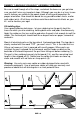
The AC signal shown is what standard 120 volt house AC power ‘looks’ like. The voltage of 120 volts is what is called RMS (Root Mean Squared) voltage. Notice that the voltage goes up to a peak voltage of about 170 volts, goes down to 0 and then goes to 170 volts in the opposite direction. The RMS value is a complicated value determined with calculus and represents the equivalent DC voltage of the peak voltage of 170 volts.
As described earlier a capacitor will block the flow of a DC current but will appear to conduct and AC current. However it is not an absolute short circuit to AC and actually changes its resistance with changes in the frequency of the signal. In an AC circuit resistance is call impedance and can be plugged into Ohm’s Law in place of the resistance values. To calculate the impedance of a capacitor, we’ll call it ‘Zc’, of a capacitor the formula is: Zc = 1 / {(2 * pi) * f * C} Zc = 1 / 6.
inductive and they cause problems with any output devices. The only other output consideration is if C2 is required. The basic function of C2 is to fill in the gaps of an AC input signal and keep the output in it’s active state during the time an AC signal is at a low level. The larger the value of C2 the bigger the gap can be and the output will not change.
CONCLUSION We sincerely hope that you will enjoy the use of this Ramsey product. As always, we have tried to compose our manual in the easiest, most “user friendly” format possible. As our customers, we value your opinions, comments, and additions that you would like to see in future publications. Please submit comments or ideas to: Ramsey Electronics, LLC. Attn. Hobby Kit Department 590 Fishers Station Drive Victor, NY 14564 or email us at: techsupport@ramseyelectronics.
OM2 SPECIFICATIONS Input Requirements: >=1.5 volts DC or >=1.5 volts peak AC at 1mA to 60mA depending on application Input to Output Isolation: 5000 volts maximum Switching Rate: DC to 250kHz Output Configuration: Active High DC or Active Low DC Maximum Load: 40 VDC max @ 150mA max Dimensions: Board: Mounting: Weight: 1.5in (W) X 2.5in (L) X 0.875in (H) 31.1mm (W) X 63.5mm (L) X 22.2mm (H) 4 holes, 4/40 screw clearance on 1” x 2” pattern 4 holes on 25.4mm x 50.8mm pattern 0.7 Oz, 0.
THE RAMSEY KIT WARRANTY 1. GENERAL: Notice that this is not a "fine print" warranty. We want you to understand your rights and ours too! All Ramsey kits will work if assembled properly. The very fact that your kit includes this new manual is your assurance that prior to release of this kit, a varied group of knowledgeable people have assembled this kit from scratch using this manual.
Quick Reference Introduction/Circuit Description .......................4 Parts Layout Diagram .....................................7 Parts List .........................................................9 Assembly Steps.............................................10 Schematic................................................ 12-13 Configuring Your OM2 ..................................16 Specifications ................................................