
Instruction manual


OM2 15
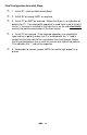
Final Configuration Assembly Steps
1. Install R1, value as determined above
2. Install R2 or jumper JMP1 as required.
3. Install C1 or JMP2 as required. Notice that there is no indication of
polarity for C1. If an electrolytic capacitor is used make sure to install it
so the “+” terminal is installed in the hole that is on the side electrically
nearest the positive connection of the input signal.
4. Install C2 as required. If the required capacitor is an electrolytic
type and has a polarity make sure it is installed with the “+” lead in-
serted into the hole next to the + printed on the circuit board. Notice
that the printed pattern has a small fat area on one side of the pattern.
This indicates the “-“ side of the capacitor.
5. Remember to remove jumper JMP3 if an active high output is re-
quired.