UNIVERSAL AUDIO AMPLIFIER SYSTEM Ramsey Electronics Model No. UAM4SYS The UAM4SYS is a state of the art audio amplifier that utilizes a class D power amplifier. Professional balanced input is provided along with an unbalanced line output that can be configured as a buffered input feed thru or as the “processed”, (tone, balance, level) signal to feed remote locations. All controls use DC or digital levels, eliminating control noise. Headphone level is provided by a 64 step digital control with memory.
PARTIAL LIST OF AVAILABLE KITS: RAMSEY TRANSMITTER KITS • FM10C, FM25B FM Stereo Transmitters • AM1C, AM25 Transmitter RAMSEY RECEIVER KITS • FR1C FM Broadcast Receiver • AR1C Aircraft Band Receiver • AR2 Aircraft Band Receiver • SR2C Shortwave Receiver • AA7C Active Antenna • SC1C Shortwave Converter RAMSEY HOBBY KITS • SG7 Personal Speed Radar • SS70C Speech Scrambler/Descrambler • TT1CTelephone Recorder • MD3C Microwave Motion Detector • PH14C/15C/16C Peak hold Meters RAMSEY AUDIO KITS • SHA1C and SHA2 H
Ramsey Publication No. UAM4 Manual Price Only $5.00 KIT ASSEMBLY AND INSTRUCTION MANUAL FOR Universal Audio Amplifier System TABLE OF CONTENTS Theory of Operation........................................... 4 “Learn-As-You-Build” Kit Assembly.................. 11 Parts List.......................................................... 13 Assembly Steps................................................ 14 Setup and Testing ............................................ 24 Specifications ............................
UAM4SYS Theory of Operation Note: There are four pages of schematics included in this manual. Please refer to them as directed as you read the following. Power Supply Since electronic equipment doesn’t work without power, lets start off by describing the UAM4SYS power supply. For reference when reading this section, check schematic sheets 1 and 2 (pages 38 & 39). The UAM4SYS requires a 12 to 18 volt DC input at 3.3 amps applied to Power jack J5. From there the power goes two directions.
The input buffer allows both unbalanced and balanced input signals to be applied to the UAM4SYS. First we will take an unbalanced signal into the unbalanced input at J4. An unbalanced single is one that uses two conductors, one for the audio signal and one for ground. This is the type of signal that comes out of an MP3 player, CD player, tape deck, VCR, computer, or other similar device. J4 takes a 3.5mm Stereo plug. A 3.5mm stereo plug consists of three conductors called tip, ring, and sleeve.
and goes through C12 and R15 to U1B’s inverting input at pin 6. The right channel signal is buffered and exits at pin 7. J2 and J3 can also be used as unbalanced inputs by simply connecting an unbalanced input to the connector tip and the ground to the ring and sleeve. The signal will now be applied to the ‘-’ input of the op amps and the op amp ‘+’ inputs will be tied to ground. This is handy if you have inputs that use separate left and right cables and mono 3.5mm plugs.
U5A is a flip flop set up in the toggle mode. Its outputs at pin 6, called ‘Q’, and pin 7, called ‘Q not’ indicated by a line over the Q symbol, are opposite DC levels of either +5 volts or 0 volts. R27 is a pull up resistor for the flip flop’s set line. C32 delays the +5 volts to U5A’s set line ensuring it comes up in the set condition, which is +5V on output ‘Q’ at pin 6 and 0V on pin 7, ‘Q not’, when power is first turned on.
jacks. Therefore if you are using the line outputs to record a program you can mute the speakers but continue to record the input. If you are feeding another amplifier the mute function on the UAM4SYS will silence only the local amplifier output. Headphone Amplifier U11 and U12 (sheet 2) are 750mW headphone amplifiers. C45 is a power supply filter capacitor. C33, C37, C34, and C38 are coupling capacitors. C35 and C36 are bypass capacitors.
Class AB amplifier. All power devices in a Class D amplifier are operated in on/off mode. The term usually applies to devices intended to reproduce signals with a bandwidth well below the pulse switching frequency which in our case is about 200kHz. The MAX9708 converts the input signal to a sequence of pulses whose averaged value is directly proportional to the instantaneous amplitude of the signal.
The ‘GAIN’ jumpers, H4 and H5, are used to adjust the gain of the MAX9708. See the tables on the schematic for specific settings. The gain settings are also printed on the UAM4SYS circuit board next to the jumpers. The ‘MUTE’ input terminal located below the left and right channel inputs is used to place the UAM4SYSinto the mute mode. The mute mode causes the output transistors to stop switching.
That’s about it. The rest of the components are simply support components required by the MAX9708 and are used to provide stable voltages and signals generated within the MAX9708. Again if you want more in depth information about the MAX9708 go to “www.maxim-ic.com” and locate the data sheet for it. RAMSEY Learn-As-You-Build KIT ASSEMBLY Successful kit assembly requires close attention to the assembly the assembly instructions, good soldering techniques and proper tools. Here are some helpful suggestions.
SURFACE MOUNT COMPONENT SOLDERING INSTRUCTIONS: You’ll notice that the circuit board contains only a few holes for component leads to pass through. This is because the SMT components will be affixed to the TOP side of the PC board, the side with the white printing. Be aware that the component view for assembly is looking at the TOP side of the PC board. Patience is the key when installing surface mount components.
UAM4SYS PARTS LIST Sort and “check off” the components in the boxes provided. We do our best to pack all our kits correctly but it is possible that a mistake has occurred and we missed a part. Please note that physical descriptions of parts are for those currently being shipped. Sometimes the parts in your kit may have a different appearance but still have the same values. Do not separate Surface Mount parts from their packaging until installation. CAPACITORS 3 0.
1 1 1 1 1 1 2 1 74HC109 [marked 74HC109] (U5) CD4066DCN [marked CD4066] (U6) DS1669 [marked DS1669] (U10) 7810 [marked 7810] (VR1) 7805 [marked 7805] (VR2) MMBT3906 [marked 2A] (Q3) Preinstalled LM4875M [marked LM4875M] (U11, 12) Preinstalled MAX9708 [marked MAX9708] (U7) Preinstalled MISCELLANEOUS 4 3 Pin Header (H1, 2, 4, 5) 1 2 Pin Header (H3) 2 RCA Jack (J1, 8) 4 3.5 mm Phone Jack (J2, 3, 4, 20) 1 2.
them and the circuit has been pre-tested at the factory for you. Due to circuit requirements U7’s support parts are also SMT. GF. GROUNDING FINGER INSTALLATION I know you are anxious to start soldering parts but first let’s install the beryllium grounding fingers in the case bottom. These fingers have glue that needs to set before the circuit board can be installed in the case. Let’s use our time efficiently by using the time we are going to take installing parts to also let the glue set on the fingers.
2. Install R23, another 10K ohm resistor (marked Brown, Black, Orange). 3. Install R1, yet another 10K ohm resistor (marked Brown, Black, Orange). 4. Install R24, the last 10K ohm resistor (marked Brown, Black, Orange). 5. Install R11, a 470K ohm resistor (marked Yellow, Violet, Yellow). 6. Install R14, the last 470K ohm resistor (marked Yellow, Violet, Yellow). 7. Install U1, the LMC660AIN quad operational amplifier IC (marked LMC660AIN).
15. Install J3, the last 3.5mm stereo phone jack in this section. LOB. LINE OUTPUT BUFFER CIRCUIT 1. Install R33, a 1K ohm resistor (marked Brown, Black, Red). 2. Install R32, another 1K ohm resistor (marked Brown, Black, Red). 3. Install R4, a 1M ohm resistor (marked Brown, Black, Green). 4. Install R30, the last 1M ohm resistor (marked Brown, Black, Green). 5. Install C46, a 0.1uF ceramic capacitor (marked 104). 6. Install H1 a 3 pin header.
to properly seat the IC. Now solder the rest of the pins. Check for any solder bridges when you’re done. 6. Install C26, a 0.22uF ceramic capacitor (marked 224). 7. Install C3, a 0.01uF ceramic capacitor (marked 103). 8. Install C7, a 0.22uF ceramic capacitor (marked 224). 9. Install C19, a 0.39uF metal film capacitor (marked 394). Metal film capacitors are like ceramic capacitors, they have no polarity. 10. Install C21, a 0.01uF ceramic capacitor (marked 103). 11. Install C15, the last 0.
you remembered to check polarity! 7. Install C35, a 1uF electrolytic capacitor (marked 1uF). 8. Install C36, the last 1uF electrolytic capacitor it this circuit (marked 1uF). 9. Install C33, a 100uF electrolytic capacitor (marked 100uF). 10. Install C34, the last 100uF electrolytic capacitor it this circuit (marked 100uF). 11. Install J20, the last 3.5mm stereo phone jack. M. MUTE CIRCUIT 1. Install R22, a 2.2K ohm resistor (marked Red, Red, Red). 2. Install R21, another 2.
8. Install C42, a 0.1uF ceramic capacitor (marked 104). PS. POWER SUPPLY CIRCUIT 1. Install R29, the last 2.2K ohm resistor (marked Red, Red, Red). 2. Install C28, a 10uF electrolytic capacitor (marked 10uF). That’s right, watch the polarity. You are getting good at this. 3. Install J5, the 2.1mm power jack. Make sure it is flush and square to the board before soldering. 4. Install S1, a DPST power switch.
6. Find the 5” length of 18 gauge wire. Strip ¼ inch of the insulation from each end. Twist the little wires together and lightly tin each end. Solder one end of the wire in the hole at JP2. 7. Route the wire below C37, C9, C22, and C4 and continue on above C16 and straight down to JP1 just above power switch S1. 8. Solder this end of the wire in the hole at JP1. FPB. FRONT PANEL CIRCUIT BOARD It is time to assemble the front panel.
1. Locate one of the bezels. (the bezel is the black plastic piece in which the front panel or back panel sits). The bezel has a smooth side and a side with ridges on it. The smooth side is where you place the front panel and the ridged side fits onto the case bottom. The ridges help align the bezel and panel. Place the front panel into the bezel so that the bezel can be screwed to the case bottom. 2. Now the front panel/bezel assembly will be mounted onto the case bottom.
solder a pin on J6 on the top side of the main circuit board to hold things in place. 6. Carefully slide the circuit board assembly out of the case bottom. Solder the rest of the pins on J6 and J9 on both the top and bottom of the main circuit board. 7. Insert D1, D3, D4, and D5; red LED’s into the front panel circuit board. LED’s are polarity sensitive and MUST be installed in the proper direction.
6. Remove the main/front panel circuit board assembly from the case bottom and check the back of the main circuit board for solder bridges. 7. Reinstall the circuit boards assemble into the case bottom. UAM4SYS SET-UP AND TESTING REQUIRED EQUIPMENT 12 to 18 Volt Power Supply with a 2.1mm power plug (+) center pin Headphones with a 3.5mm Stereo Phone plug Unbalanced stereo audio source with 3.
GAIN H4 H5 +22dB 1-2 2-3 +25dB 2-3 2-3 +29.5 dB 2-3 1-2 +36dB 1-2 1-2 SET-UP Connect headphones to J20. Connect a stereo audio source in one of the three configurations below: Unbalanced audio (3.5mm stereo plug) Connect an unbalanced audio source to J4. Unbalanced audio (two 3.5mm mono plugs required for stereo) Connect the left channel plug to J3. Connect the right channel plug to J2. 3.5mm stereo plugs can be substituted by making both the ring and sleeve ground. Balanced audio (two 3.
Unbalanced Balanced Stereo Tip Signal Positive Left Ring Ground/No Conn. Negative Right Ground Ground Ground Sleeve Connect speakers to T1. As you look at the back of the unit the left most contact of T1 is Left (+), the second contact is Left (-), the third contact is Right (+), and the right most contact is Right (-). Make sure to match these polarities to your speakers. DO NOT for any reason short the speak wires.
Input Buffer, Headphone Amp, Loudness, and Tone/Volume/Balance Circuits Once the power supply is plugged in and the audio input source is turned on you should be able to hear audio in the headphones (even with the power, S1, switch off). If you cannot press and hold HEADPHONE LEVEL UP switch until audio is heard. Press the HEADPHONE LEVEL Down button to test for function. Test the bass, treble, balance, and volume control for proper function. Check the Loudness control for proper function.
LED D1 illuminates. Turn off unit. Adjust jumpers at H4 and H5 for best control of audio amplifier with the volume control. This setting will be different for different audio sources. This may take a little trial and error. Always turn off unit before moving jumpers! This completes testing. With the unit off set up jumpers at H1, H2, and H3 and the speaker output jumpers near speaker connector T1 for the desired operating conditions.
cover of the manual. Note in the following steps all VOLTAGE and RESISTANCE measurements are taken with the RED or “+” lead of the meter connected to the indicated test point. The BLACK lead or the terminal labeled “-“ or “common” of the voltmeter is connected to the outside (ground) bracket on J8. The expected reading is indicated in the “[READING = rrr]” text after the instruction to make the reading POWER SUPPLY PROBLEMS Problem: Checks: No 12 to 18 Volts Input 1.
AUDIO PROBLEMS Problem: Check: No audio from headphones only 1.First, make sure you have an audio signal applied to both left and right inputs then try pressing the headphone level up button for a second or two. If you still don’t hear any audio go to step 2. 2.Use the headphone test jig to test Pin2 on U11 and U12. If you hear audio signals go to step 3. Otherwise go to step 4. 3. Use the headphone test jig to test Pin 5 on U11 and U12.
and output jacks J1 and J8 for shorts, opens and proper placement of C17, C30, R32 and R33. Problem: Check: No audio from any output 1.First, make sure you have an audio signal applied to both left and right channel inputs. If you still don’t hear any audio remove any jumpers installed on H1 and H2 and check for audio on the headphone and speaker outputs. If you still don’t have any audio on the speaker and headphone outputs go to the “No audio from only the line output jacks J1 and J8” problem section.
all circuit foil runs on both the main board and front panel board. If you can’t find anything wrong it is possible that U3 is defective but first let’s check one more thing. Turn all the controls fully clockwise and check the voltage again. If you find it is correct go to step 4, otherwise go to step 3. 3. Because the voltage changed with the setting of the controls there appears to be a problem with one or more or more of the wiper, or center pin connections, on one or more of the controls.
2. Measure the voltage on the actual terminal from the front of the front panel board, not at the circuit board of R17. [READING = 5.4VDC] If not correct go to step 3 otherwise re-solder the connection on R17. 3. While adjusting R17 measure the voltage on the center connection of R17. [READING varies between 0 and 5.4VDC] If correct measure the voltage on U3 pin 4 while adjusting R17. [READING varies between 0 and 5.
[READING varies between 0 and 5.4VDC] Otherwise check for opens, shorts and incorrect component installation, C26, R13 and R20 and connected circuit paths or U3 may be defective. Problem: Loudness control only not functioning properly Checks: 1. Measure the voltage on U3 pin 17, [READING = 5.4VDC] If correct go to step 2, otherwise go to the “Improper operation of bass, treble, balance, loudness and volume controls” troubleshooting section. 2.
(mute) button. The reading should be 0VDC with the button pressed and +5VDC when not pressed. If this is not the case check all connections and components between pin 4(12) and the push button for opens, shorts and incorrect installation. 3. If only the loudness (mute) LED does not turn on and off but the functions operate properly go to step 5. 4. While measuring the voltage at U5 pin 6(10) press the loudness (mute) pushbutton one time.
may result in voiding your warranty. Please contact our technical support department for further information. CONCLUSION As our customers, we value your opinions, comments, and additions that you would like to see in future publications. Please submit comments or ideas to: Ramsey Electronics, LLC Attn. Hobby Kit Department 590 Fishers Station Drive Victor, NY 14564 or email us at: techsupport@ramseyelectronics.
Power: Over temp: Efficiency: Audio Input: Connector: L/R: Impedance: Gain: Distortion: Modulation Scheme: ON/OFF with LED indicator LED indicator Up to 87% 3.5mm (x1) stereo unbalanced (left & right) 3.5mm (x2) stereo balanced/unbalance (Separate left & right connectors) Greater than 10K ohms balanced or unbalanced (Each channel) Selectable 22dB, +25dB, +29.5dB, +36dB O.
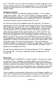
REC RIGHT LEFT LINE OUT REC LEFT RIGHT LINE OUT Schematic Sheet 1/4—Input Processing UAM4SYS • 38
Schematic Sheet 2/4—Control and Headphone Amps UAM4SYS • 39
Schematic Sheet 3/4—Front Panel 3 UAM4SYS_Rev3_4(4 sheets).
Parts highlighted in grey Pre-Installed (not shown on Parts layout) Schematic Sheet 4/4—Power Amp UAM4SYS • 41
Parts Layout UAM4SYS • 42
THE RAMSEY KIT WARRANTY 1. GENERAL: Notice that this is not a "fine print" warranty. We want you to understand your rights and ours too! All Ramsey kits will work if assembled properly. The very fact that your kit includes this new manual is your assurance that prior to release of this kit, a varied group of knowledgeable people have assembled this kit from scratch using this manual.
QUICK REFERENCE Theory of Operation .......................................... 4 Parts List.......................................................... 13 Assembly Steps................................................ 14 Setup and Testing ............................................ 24 Specifications ................................................... 36 Schematics ..................................................38-41 Parts Layout Diagram.......................................