
Instruction manual


UAM4SYS • 22
1. Locate one of the bezels. (the bezel is the black plastic piece in which
the front panel or back panel sits). The bezel has a smooth side and a
side with ridges on it. The smooth side is where you place the front panel
and the ridged side fits onto the case bottom. The ridges help align the
bezel and panel. Place the front panel into the bezel so that the bezel can
be screwed to the case bottom.
2. Now the front panel/bezel assembly will be mounted onto the case
bottom. Remember that case bottom? We put the beryllium fingers on it
way back in steps GF1- GF6. You must first identify which end of the
case bottom is the front. Notice that the fingers installed in step GF1 –
GF6 are flexible and folded. The BACK of the case bottom is the end
toward the adhesive on the fingers. (See picture after step GF6.) The
front is the other end where the front panel/bezel is to be mounted. We
will use the front panel/bezel assembly from step BA1, and the case
bottom from step GF6. Before assembling the parts you’ll want to peel
the protective plastic from the front panel. The front panel sits inside the
bezel; the included black screws go first though the front panel then the
bezel holding the assembly to the case bottom. Align the holes of the
front panel, bezel, and case bottom front (upper slot) and insert the black
screws.
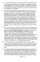
3. It is now time put our front panel circuit board and main board together.
Slide the main board between the two rows of long pins on J40 and J7 on
the front panel circuit board so that J6 and J9, respectively, on the main
board are aligned. DO NOT SOLDER the connectors at this time.
Now it is time to align the front panel controls with the front panel.
Carefully slide the front panel circuit board and main circuit board
assembly, from step BA3, into the front panel/case bottom assembly from
step BA2. Line up the front panel circuit board so the switches and
potentiometers extend out through the front panel of the case. Make sure
the front edges of the main circuit board are seated firmly against the back
side of the front panel. This is important because it will not be possible to
install the rear panel if there is any space between the two.
4. Slide the front panel circuit board back and forth until all switches,
buttons and the 3.5mm jack are centered in the front panel holes. When
everything is neat and right where you want it to be, take your soldering
iron and solder one of the pins of J9 on the top side of the main circuit
board.
5. Check the alignment one more time because once you make the next
solder connection it will be difficult to take the boards apart. Make sure
the front panel circuit board is square and not angled with respect to the
main board and parallel with the front panel. Make sure that the main
circuit board front left and right tips (under S1 and J20) touch the back
side of the front panel. When you are satisfied that everything is correct