4-19.5 MHz SHORTWAVE RADIO Ramsey Electronics Model No. SR2 Have you ever wanted to get into the fascinating world of radio? The Ramsey SR2 is a fine performer that will bring in the world using just a few feet of wire as an antenna! Folks of all ages have successfully built and enjoyed this easy and fun kit. • Enjoy hours of fascinating international listening using just a simple indoor wire antenna • Select portions of the 4 to 19.
PARTIAL LIST OF AVAILABLE KITS RAMSEY TRANSMITTER KITS • FM10A FM Stereo Transmitter • FM100B Professional Synthesized FM Stereo Broadcaster • FM25B Synthesized FM Stereo Transmitter • AM25 Synthesized AM Transmitter • AM1 AM Transmitter RAMSEY RECEIVER KITS • FR1 FM Broadcast Receiver • AR1 Aircraft Band Receiver • AA7 Active Antenna • SC1 Shortwave Converter RAMSEY HOBBY KITS • SG7 Personal Speed Radar • SS70A Speech Scrambler • TT1 Telephone Recorder • SP1 Speakerphone • MD3 Microwave Motion Detector • P
Ramsey Publication No. MSR2 Manual Price Only: $5.00 KIT ASSEMBLY AND INSTRUCTION MANUAL FOR 4-19.5MHz SHORTWAVE RADIO TABLE OF CONTENTS Introduction to the SR2 ........................................ 4 What You Can Expect to Hear ............................. 4 Shortwave Listening as a Hobby ......................... 5 Circuit Description................................................ 6 Parts Layout Diagram .......................................... 8 Block Diagram .....................................
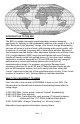
INTRODUCTION TO THE SR2 The SR2 is a single-conversion superheterodyne receiver designed specifically for listening to AM broadcasting stations in the range of 4 to 19.5 MHz. Because of this "superhet" design, your favorite foreign broadcasting services will come in loud and clear, with pleasing audio sound quality, with a minimum of overload, frequency drift or heterodyne whistles.
• BBC London: an intelligent perspective on world affairs • Radio Canada International: editorial quality similar to BBC • Radio Moscow: powerful signals, increasingly honest and open • Voice of America: VOA broadcasts are "aimed" outside the USA, but if you're in the "path" you'll hear it loud and clear! • U.S. Armed Forces Radio-TV "Feed" Service: Master programming source for U.S.
you, you'll be in a better position to choose a more elaborate receiver. While there are various multi-band portable radios available, you can expect to pay at least $100 for a receiver offering a significant improvement over your trusty SR2. To learn more about this SWL hobby, look for a copy of "Popular Communications" at newsstands. An inexpensive and interesting general introduction to all kinds of radio listening is the book, "Shortwave Listening Guide" by William Barded, Jr.
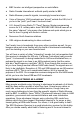
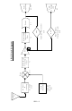
varactor diode tuning. The varactor (D3) forms an L/C (Inductor/Capacitor) tank circuit with T3. Increasing the voltage on the varactor diode with R21 (Tuning Pot) increases the capacitance of D3 thus increasing the frequency output of the LO section. Now that we know the two signals coming into the Mixer stage, both the Fc (receive carrier frequency) and the LO (generated local oscillator), we can better cover its operation. The mixer takes these input signals and performs a few very basic operations.
RSSI circuit is controlled by the value the feedback resistor R17. If you are commonly using a small antenna and listening to weak signals, increase the value of R17 to customize the response indication of D2, the signal strength LED. The final stage, and the real secret to the sensitivity of the receiver, is the Automatic Gain Control (AGC). The gain control looks at the amount of signal level present at the output of the demodulator and varies the amount of gain the Amplifier has accordingly.
SR2 – 9 J1 A n te nn a T1 C 1 ,C 2 ,C 3 L 1 ,L2 C 1 5 ,C 1 6 R21 T 3,D 3 ,Q 3 O scilla to r L o ca l F req ue ncy F ilte r & F ilte rin g Q1 In te rm e d iate R F In pu t M ix e r Q2 Am p AGC D1 D e m od U 1 :B S tren g th Ind ic a to r R ece ive S ig n al RSSI U 1 :A A u to m atic G a in C o n trol T2 F ilte r F req ue ncy In te rm e d iate S R -2 B lo c k D ia g ram D2 S tren g th LED S ig n a l U 2 , J2 A u dio (S p e ak er)
PARTS LIST CAPACITORS 1 10 pF ceramic disc capacitor [marked 10] (C30) 1 47 pF ceramic disc capacitor [marked 47] (C15*) 4 100 pF disc capacitor [marked 100, 101, or 100K] (C5,15*,16*,17) 1 330pF disc capacitor [marked 330 or 331] (C2) 6 .001µF disc capacitors [marked .001, 102, or 1nF] (C1,3,16*,20,21,25) 1 .0039 uF disc capacitor [marked 392 or 392K] (C31) 4 .01µF disc capacitors [marked .01, 103, or 10nF] (C4,6,8,28) 6 .1µF ceramic disc capacitor [marked .
HARDWARE AND MISCELLANEOUS 1 SR2 printed circuit board 2 10K potentiometers (R14,21) 1 DPDT PC-mount push button switch (S1) 1 RCA-type PC-mount jack (J1) 1 Subminiature phone jack (J2) 1 9-volt battery snap connector 1 9-volt battery hold-down clamp REQUIRED, NOT SUPPLIED: 9-volt alkaline or heavy-duty battery Earphone, small speaker, or external amplifier with speaker Antenna or suitable cable, connector, grounding OPTIONAL Ramsey SR2 case and knob set (CSR), or your own enclosure SR2
ASSEMBLY INSTRUCTIONS In ALL PC-board assembly steps, our word "INSTALL" means to do this: Insert the part, oriented or "pointed" correctly, into its holes in the PC board. If helpful, gently BEND the part's wire leads or tabs to hold it in place, with the body of the part snugly against the top side ("component side") of the circuit board. Solder ALL wires or pins of the part.
We will now begin constructing the local oscillator section. 5. Install C22, one of the 10µF electrolytic capacitors. Electrolytic capacitors have a right and wrong way to be installed. Usually, capacitors have a wide stripe which indicates their negative lead and the PC board or Parts Layout Diagram will show the positive side of the capacitor's installation hole. Be sure to place the ( + ) capacitor lead into the PC board ( + ) hole and the ( - ) lead into the ( - ) hole before soldering. 6.
SR2 – 14
SR2 – 15
jumped ahead and installed T3, we've got bad news for you). Before this shielded transformer can be installed, its internal capacitor needs to be removed. Looking at the underside of this transformer, you'll see a tubular part, probably white with a brown band, somewhat like the resistors in this kit. This is brittle and easily crushed with any sharp object that can be pressed against it with mild force (small nail, nutpick, small screwdriver).
33. Install R2, 22K ohms [red-red-orange]. 34. Install R1, 100K ohms [brown-black-yellow]. 35. Install C24, 1µF electrolytic capacitor. Remember to watch polarity when installing. 36. Install C5, 100 pF disc capacitor [marked 100, 101, or 100K]. 37. Install C4, .01µF disc capacitor [marked .01, 103, or 10nF]. 38. Install R26, 100 ohms [brown-black-brown]. 39. Install C23, 10 µF electrolytic. Remember to check the polarity before installing. 40. Install Q2, the last 3904 transistor.
58. Install C9, 1µF electrolytic capacitor. Check polarity when installing. 59. Install C11, 10 µF electrolytic. Observe correct polarity before installing. 60. Install R16, 270 ohm [red-violet-brown]. PROGRESS SUMMARY Now is a good time to take a break. Examine your work so far checking things such as component values, parts placement, and solder connections.
72. Install the battery clamp. Position battery and holder so as not to cover nearby PC board mounting holes. Use the method for securing the clamp that is most convenient for you, such as: • wire looped through clamp and PC board holes, soldered. • small screws • double-faced adhesive strips • hot-melt glue 73. If you desire increased audio output, C27, 10 µF, may be installed. Be sure the (+) and (-) leads are inserted correctly. 74. We’re at the end now, just one part left to install.
provide a ground connection. 4. If an indoor antenna is necessary, simply make it as long as possible and as high up from concrete floors as you can. 5. When installing any outdoor antenna, BE VERY CAREFUL not to let your antenna wire come in contact with electric power lines. 6. Any antenna wire for shortwave listening may run horizontally, vertically or some both ways, or at an angle! 7. If you have a roof-mounted TV antenna, its feedline will make a great antenna for your SR2. 8.
4. Turn ON the receiver. After adjusting the volume to a pleasant level, you should hear some shortwave stations by turning the Tune Control, no matter how any of the adjustable coils happen to be set. While listening to any kind of station, whether broadcast or Teletype, etc., use a small screwdriver to adjust the slugs in transformers T1 and T2 for the best-sounding reception. The Tuning Control covers varying segments of the bands selected by adjustment of oscillator coil T3.
reception. Eventually, you will get a clue as to what general frequency band you are hearing, because many stations periodically announce their frequencies, particularly at sign-on and sign-off times. If you like precision, use a frequency counter or calibrated receiver to find the SR2's strong oscillator signal, remembering that there is a 455 KHz IF difference (above or below) between the local oscillator frequency and the broadcast signal you are hearing.
THE RAMSEY ELECTRONICS CASE, KNOB & HARDWARE OPTION Your finished receiver can be installed in a variety of enclosures of your own design and choosing. You might be planning to combine several Ramsey circuit kit boards in a single enclosure. Use of the inexpensive and attractive Ramsey case and knob kit will give your unit that finished look and increase its resale value. These sturdy black instrument cases are supplied with neatly lettered front and rear panels, knobs, rubber feet and mounting screws.
SAMPLE SHORTWAVE LOGGINGS Freq Country (MHz) 4.30 4.31 4.38 4.40 4.72 4.72 4.78 4.78 4.82 4.82 4.97 5.04 5.50 5.67 5.76 6.01 6.02 7.11 7.12 7.12 8.45 9.02 9.34 9.90 9.90 9.90 9.92 11.60 12.00 13.64 13.65 15.14 16.00 17.49 17.67 17.67 17.67 17.
SAMPLE SHORTWAVE LOGGINGS Con’t Freq Country (MHz) Notes/Contributor 18.96 18.96 SWEDEN SWEDEN 18.96 18.
SR2 – 26
The Ramsey Kit Warranty Please read carefully BEFORE calling or writing in about your kit. Most problems can be solved without contacting the factory. Notice that this is not a "fine print" warranty. We want you to understand your rights and ours too! All Ramsey kits will work if assembled properly. The very fact that your kit includes this new manual is your assurance that a team of knowledgeable people have field-tested several "copies" of this kit straight from the Ramsey Inventory.
SR2 Shortwave Receiver Quick Reference Page Guide Introduction to the SR2 .......................4 What You Can Expect to Hear ............4 Shortwave Listening as a Hobby .........5 Circuit Description ...............................6 Parts Layout Diagram .........................8 Parts List .............................................10 Assembly Instructions .........................12 Schematic Diagram .............................14 Shortwave Antenna Ideas ...................