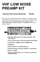
VHF LOW NOISE PREAMP KIT Ramsey Electronics Model No. PR100 Boost up those weak signals without adding in unwanted noises! The PR100 has a three section tuned circuit and a double helical filter to allow only the desired signal to be amplified, while attenuating signals outside the band. A perfect match for any 2 meter receiver! • Extensive filtering for low noise operation, 1dB noise figure! • Three section tuned circuit and double helical filter • Centered on 145 MHz and is 2.
RAMSEY TRANSMITTER KITS • FM100B Professional FM Stereo Transmitter • FM25B Sythesized Stereo FM Transmitter • MR6 Model Rocket Tracking Transmitter • TV6 Television Transmitter RAMSEY RECEIVER KITS • FR1 FM Broadcast Receiver • AR1 Aircraft Band Receiver • SR2 Shortwave Receiver • SC1 Shortwave Converter RAMSEY HOBBY KITS • SG7 Personal Speed Radar • SS70A Speech Scrambler • BS1 “Bullshooter” Digital Voice Storage Unit • AVS10 Automatic Sequential Video Switcher • WCT20 Cable Wizard Cable Tracer • LABC Lea
Ramsey Publication No. MPR100 Manual Price Only: $5.00 KIT ASSEMBLY AND INSTRUCTION MANUAL FOR VHF LOW NOISE PREAMP KIT TABLE OF CONTENTS Introduction to the PR100 ............................. 4 How it Works ................................................. 4 Schematic ..................................................... 5 Parts Layout .................................................. 6 Strategy ......................................................... 7 Assembly Steps .................................
INTRODUCTION TO THE PR100 This amplifier is a truly necessary piece of equipment for your 2 meter receive applications. With 16dB of gain, you mount this up on your mast on the antenna to boost those weak signals to a receivable level. This results in clear, unbroken reception, and a more pleasant listening experience. The filtering of the preamplifier is narrow enough only to allow the desired frequency band through, while rejecting all others.
The RF passes through two more tank circuits consisting of L4 and C9 in the second, and C12 and L5 in the third. Every time the RF goes through an additional tank circuit, the bandpass bandwidth of the RF is narrower. The narrower the bandwidth is before the active component of Q1, the better. The narrow bandpass allows Q1 to devote its amplification to just the desired signals. This means that it doesn’t amplify nearly as much noise, and won’t amplify signals outside of the bandpass area.
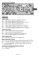
PARTS LAYOUT DIAGRAM PARTS LIST CAPACITORS 2 2.2pF ceramic capacitors (marked 2.2) (C4, C5) 1 10pF ceramic capacitor (marked 10) (C7) 3 8.2pF ceramic capacitors (marked 8.2) (C8, C9, C10) 1 22pF ceramic capacitor (marked 22) (C6) 1 100pF ceramic capacitor (marked 100, or 101) (C2) 1 .001uF ceramic capacitor (marked .001, or 102) (C3) 1 .01uF ceramic capacitor (marked .
RAMSEY "LEARN-AS-YOU-BUILD ASSEMBLY STRATEGY" We'll start building on the left side and work our way across, installing the lower components up to the taller sized components. This will make our placing and soldering of components easy. Be sure to read through all of the steps, and check the boxes as you go to be sure you didn't miss any important steps. Before you connect up the kit in a hurry to see results, check all diodes, ICs, and capacitors for proper orientation.
ASSEMBLY INSTRUCTIONS: 1. Orient the PC board as in the Parts Layout Diagram. We will start with the left hand side of the board, then go to the right. 2. Install C6, the 22pF ceramic capacitor (marked 22). 3. Install C8, a 8.2pF ceramic capacitor (marked 8.2). 4. Install C4, a 2.2pF ceramic capacitor (marked 2.2). 5. Install C9, a 8.2pF ceramic capacitor (marked 8.2). 6. Install C5, another 2.2pF ceramic capacitor (marked 2.2). 7. Install C10, yet another 8.2pF ceramic capacitor (marked 8.2).
18. Install C1, a .01uF ceramic capacitor (marked 103, .01, or 10n). 19. Install L2, another 2.2uH inductor (green body, red-red-gold stripes). 20. Install R3, a 18 ohm resistor (brown-grey-black). 21. Install C3, a .001uF capacitor (marked 102, or .001). 22. Install R5, a 300 ohm resistor (orange-black-brown). 23. Install FL1, the two section helical filter. Make sure and mount it firmly to the board, and that all leads are soldered correctly.
ALIGNMENT: Alignment is fairly simple if you follow these guidelines. The first step is to back all of the lugs out of L3, L4, and L5 until they reach the top of the cans. FL1 should be ok, and won’t need any adjusting. 1. Screw L3 in 8 turns. 2. Screw L4 in 8 turns. 3. Screw L5 in 8 turns. If you have the equipment and the know-how, you can adjust the coils and the helical filter further. You will need a spectrum analyzer and a frequency generator to run at 145.52 MHz for best alignment.
PREAMP INSTALLATION This part of the manual assumes that you have a receiver or transceiver (if using a transceiver a TR Switch is needed, like our RFS-1). This preamp operates off a 12 volt DC supply which is connected to a 2.2 µH inductor then to the center of the antenna cable near your radio(see diagram on next page). Care has to be taken so that you don’t short out any connections. Also a .01µF ceramic capacitor must be installed after the radios’ output and before the connection to the 12 volt supply.
THE PR100 Hookup is simple if you are using coax cable such as RG-58 or better 50 ohm cable. Just run a piece from the jack marked RCVR (J3) on the PR100 to the .01µF capacitor just before the radio. Then a short piece is needed to go from the capacitor to the radio. Finally, you need to connect the Preamp to the antenna and you are ready for testing. HOOKUP EXAMPLE Turn on your receiver, you should be able to pick up a weak signal with little difficulty.
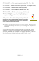
TROUBLESHOOTING GUIDE: <-- To Antenna To Radio --> Problem: When I insert this in line, I don’t observe any gain in reception. Solution: There are several causes to the problem, but the major one is that the preamp has been assembled incorrectly. Check Q1 for correct installation, then check J3 for 12VDC. If those check out, go through assembly steps again to make sure you have the parts where they belong.
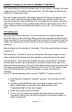
The Ramsey Kit Warranty Please read carefully BEFORE calling or writing in about your kit. Most problems can be solved without contacting the factory. Notice that this is not a "fine print" warranty. We want you to understand your rights and ours too! All Ramsey kits will work if assembled properly. The very fact that your kit includes this new manual is your assurance that a team of knowledgeable people have field-tested several "copies" of this kit straight from the Ramsey Inventory.
4. BE accompanied by the proper repair fee. No repair will be undertaken until we have received the MINIMUM repair fee (1/2 hour labor) of $25.00, or authorization to charge it to your credit card account. 5. INCLUDE a description of the problem and legible return address. DO NOT send a separate letter; include all correspondence with the unit. Please do not include your own hardware such as non-Ramsey cabinets, knobs, cables, external battery packs and the like. Ramsey Electronics, Inc.
VHF LOW NOISE PREAMPLIFIER Quick Reference Page Guide How it Works ....................................... 4 Schematic ............................................ 5 Parts Layout ........................................ 6 Strategy ............................................... 7 Assembly Steps ................................... 8 Troubleshooting ................................... 13 Warranty ..............................................