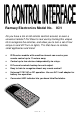
Ramsey Electronics Model No. ICI1 Do you have a ton of old remote controls around, or even a universal remote? Put those to real use by training this unique kit to recognize the remotes, and allow you to turn a set of four relays on and off! Turn on lights, TVs that have no remote, small appliances and more! • IR Receiver module with sensitive element can receive your remote control up to 11 meters away. • • • • Control up to four devices independently via relays.
RAMSEY TRANSMITTER KITS • FM10A, FM25B FM Stereo Transmitters • FM100B Professional FM Stereo Transmitter • TXE433 or 916 Transmitter & Encoder Module • RXD433 or 916 Data Receiver& Decoder • RR1 Wired remote repeater • RRW1 Wireless remote repeater RAMSEY RECEIVER KITS • FR1 FM Broadcast Receiver • AR1 Aircraft Band Receiver • SR1 Short-wave Receiver RAMSEY HOBBY KITS • WEB1 Walking Electronic Bug • LEDS1 LED Strobe • BE66 Blinky Eyes • EDF1 Electronic Dripping Faucet • TFM3 Tri-Field Meter • LC1 Inductanc
Ramsey Publication No. MICI1 Price $5.00 KIT ASSEMBLY AND INSTRUCTION MANUAL FOR ICI1 IR CONTROL INTERFACE KIT TABLE OF CONTENTS Introduction ...........................................4 Theory of Operation ..............................5 Learn As You Build ...............................7 Parts List ...............................................9 Schematic Diagram .............................10 Parts Placement Diagram ...................11 Assembly Steps...................................12 Testing....
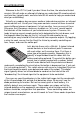
ICI1 INTRODUCTION Welcome to the ICI1 kit (and if you don’t have the time, the wired and tested version). We will make an attempt at helping you understand IR remote controls and how they typically work, and also how this kit works to help you understand what you are building. Virtually any modern day consumer audio or video device contains an infrared remote control unit. Usually our living room contains several of these to control several different pieces of equipment.
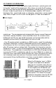
ICI1 THEORY OF OPERATION At first look the ICI1 may seem quite simple, but there is actually quite a bit to it on the “inside” of the components. Many items are inside the IR receiver part (U4) and if built up with discrete components it would never fit in this little kit case. Inside this part there’s an IR detector diode, amplifier, AGC circuit, band pass filter, a peak-hold circuit, an integrator, comparators, and an output amp.
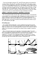
Typically a remote control will send data in a format consisting of time slices. To send a zero, the IR LED will be off for one time slice, and then toggled at a rate of 38kHz for the second time slice. To send a one, the IR remote will use three time slices. Off for two time slices, and on for one.
There are two option switches OP1, and OP2 which allow you to switch the modes of Relay 1&2 with OP1, and Relay 3&4 with OP2. If the option jumper is in, then the corresponding relays are in “auto-toggle” mode. It means that as long as the remote button is pressed, the relay will remain energized. Let go of the button, and it de-energizes the coil. The typical action of the relay is in toggle mode. Press the remote button, and the relay changes state.
Although we know that you are anxious to complete the assembly of your infrared controller kit it is best to follow the step-by-step instructions in this manual. Try to avoid the urge to jump ahead installing components. Since you may appreciate some warm-up soldering practice as well as a chance to put some landmarks on the PC board, we’ll first install some of the larger components. This will also help us to get acquainted with the up-down, left-right orientation of the circuit board.
PARTS SUPPLIED WITH YOUR ICI1 KIT Capacitors 2 10 pF ceramic capacitors (Marked 10 or 10K) (C1,8) 4 0.
ICI1 SCHEMATIC DIAGRAM ICI1 Page 10
ICI1 PARTS PLACEMENT DIAGRAM ICI1 Page 11
ICI1 REMOTE CONTROLLER INTERFACE ASSEMBLY Assembly of the ICI1 is fairly easy, as we use all through hole components, but it requires some time and some patience. We will start with the side that has the power jack, and we will move from there using the power jack as a reference. 1. Identify and install power connector J7 toward the rear of the printed circuit board.
“one-way switches” in this manner to protect internal circuitry. In our case we use the diode “double duty”, because if you use an AC wall adapter this diode will act as a half wave rectifier to provide a DC voltage to the input of the voltage regulator IC. 6. Identify C4, the 1000 uF electrolytic capacitor (cylindrical component and marked 1000 uF). Electrolytic capacitors are polarized with a (+) and (-) lead and must be installed in the correct orientation.
9. Install C7, a 0.1uF ceramic capacitor (marked 104). Disc capacitors are not polarized, so either direction is alright. 10. Install R13, 10 ohm resistor (brown-black-black). Resistors are not polarized; they may mount in either direction. 11. Identify and install the mini speaker. SP1 (small round object with two leads protruding). You may notice a “+” sign adjacent to where the leads attach, but for our application polarity is not a concern.
to use enough solder and heat for a good solder connection, and be extra careful not to “bridge” any solder connections together. It usually works best to solder the two “corner” pads first to hold the IC in place, and then work through the remaining 18 connections. Once the socket is soldered, insert the microcontroller IC into it. Pay particular attention to the orientation of this device. Make sure to align the notch or dot associated with pin one with the notch shown in the parts layout diagram.
different components. 29. Install “lay-down” 1K ohm resistors R2, R1, R3, and R4 (brown-blackred) . 30. Install “stand-up” resistors R14, R15, R16, R17, all 100 ohm (brownblack-brown). 31. Identify the remaining small signal transistors Q1, Q2, Q3, Q4 (three leads marked 3904). Notice that there is a “flat” side of the component. Install these transistors, being sure to mount the flat side as shown in the parts diagram.
TESTING AND PROGRAMMING YOUR ICI1 To begin testing the ICI1 we will need the following items: AC Power supply between 9 and 15VAC or.. DC power supply between 9 and 15VDC. A remote control Its finally time to apply power to your kit. Please be sure before you do that you clear the bench of any scrap component leads and have one final look at your solder connections before you proceed. Again, time spent here can prevent problems encountered during testing and can avoid damaging any of the components.
Set the power switch to the “off” position, and plug in a suitable power source to the power input connector. The correct range of values for supply voltage is 9 - 15 VAC or VDC, and the current capacity is between 200 - 250 mA. Our AC125 transformer is the recommended source for this kit, but any wall wart will do. Upon energizing the switch, a short chirp will be heard from the speaker and the LED should illuminate.
Back to programming. Now that the first, or digital 0,0, location has been programmed it is time to advance to the next three states. We will need to count in binary, or base two. There is no such thing as a number two in binary, only ones and zero’s (making it the choice of electronic circuits). The following chart will describe the header jumper sequence for the binary count, and we have left some room to jot down the function key you are using on your remote.
Move the jumper in the SEL 0 connection so that it is only connected to one pin, offset such that it will not make contact with the other pin in order to set the associated jumper with the logic “1”, or 5 VDC state. This sets the IC to learn in the 0, 1 state (or decimal state 1). Depress the learn button and memorize the second code. In the same manner, program the remaining two codes, incrementing the jumpers as you move along.
WIRING AND CUSTOM APPLICATION SUGGESTIONS Using your DCI1 for a variety of applications is very simple. You just need to keep in mind the ratings for the relay contacts listed on the specification page to avoid any problems and use a common sense approach for personal safety.
Typical High Power Relay: -DCI1 used to trigger another Higher Power relay. A few other important notes: It is recommended that all external connections be fused for safety, especially if you are connecting to 120VAC line voltage. Please choose the correct fuse size for your individual application. Proper fusing is critical to the safe operation of your kit, please take the time to properly insulate any high voltage or current contacts made externally to your unit.
PROBLEM: The green LED doesn’t light up when I aim my remote at it. SOLUTION: There are a few things that can go wrong here, so we will go from the most likely to the least. 1 You forgot to turn on the power, or your DC adapter isn’t compatible (the polarity is reversed). 2 You installed the green LED in backwards. Please check the orientation. 3 Your remote control’s battery is shot. Replace the battery. 4 Junior poured a coke and some ice cream into it.
Make sure that you have “checked” all the assembly steps boxes; you may have forgotten one or two of them. PROBLEM: I just can’t make the &#^$^@! thing work! SOLUTION: Call Ramsey Support at 1-585-924-4560 or look at the warranty in this manual. We are here to help and reduce your frustration as much as possible. It is usually something simple. Have your board revision handy to help our technicians find the proper schematic for your needs. You can email our tech support as well at the ramseykits.
ICI1 INFRARED CONTROLLER INTERFACE SPECIFICATIONS Here are few of the commonly requested specifications for the ICI1: J1, 2, 3, and 4 Relay Outputs - Contact Rating: 5 A, 120 VAC / 28 VDC (Resistive) - Rated Contact Current: 5 A - Max. Contact Capacity: 1250VA AC, 150W DC - Contact Arrangement: SPST-NO - Contact Material: AG Alloy - Note: Not intended for heavily inductive loads such as large motors.
ICI1 Page 26
The Ramsey Kit Warranty Please read carefully BEFORE calling or writing in about your kit. Most problems can be solved without contacting the factory. Notice that this is not a "fine print" warranty. We want you to understand your rights and ours too! All Ramsey kits will work if assembled properly. The very fact that your kit includes this new manual is your assurance that a team of knowledgeable people have field-tested several "copies" of this kit straight from the Ramsey Inventory.
ICI1 REMOTE INTERFACE KIT Quick Reference Page Guide Introduction .......................................... 4 Theory of Operation .............................. 5 Parts List ............................................... 9 Schematic Diagram............................. 10 Parts Placement Diagram ................... 11 Specifications...................................... 26 Warranty .............................................