
User's Manual


RRW1B • 12
28. Install C20, a 0.01 uF ceramic capacitor (marked 103).
29. Install R22, a 470 ohm resistor (yellow-violet-brown).
30. Install C29, a 0.001 uF ceramic capacitor (marked 102).
31. Install L21, the other 33 nH four turn inductor. This coil combined with
C28 makes the amplifier of Q20 selective, so it only amplifies the desired
frequency area of 433.42 MHz.
32. Install C28, a 10 pF ceramic capacitor (marked 10 or 10k).
33. Install C31, a 10 uF electrolytic capacitor. Check its orientation before
soldering into place.
34. Install VR20, the 78L05 voltage regulator. Make sure the flat side of
this component is in the same orientation as shown on the silkscreen. This
part works by “smoothing” out any junk that may reside on the non-
regulated input side of the part. It also allows you to run this kit from a
wide range of supply voltages while it keeps the output fixed at 5V.
35. Install D21, the large 1N4002 regulator diode. If you are using an AC
power supply, this diode helps to convert the AC source voltage to pulsed
DC. C32 (which we install last for mechanical reasons) accumulates the
pulsed DC and smoothes it out so that regulator VR20 can process it the
rest of the way and provide us with a clean power source. Make sure the
line which indicates the Cathode is installed in the same orientation as
shown on the silk screen and Parts Layout Diagram.
36. Install S20, the power switch. Solder only one pin until you are sure
the switch is flush to the board. Then solder the rest.
37. Install C32, the large 1000 uF electrolytic capacitor. Double check its
orientation before soldering as this is especially critical with this part.
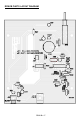
38. Install ANT1, the 6” piece of bus wire. Solder the wire in place where
the circuit board has been marked “ANT1” for easy identification. Use a
ruler and trim off any extra wire if longer then 6” (5.75 to 6.5” works great).
It looks like we have all of the holes stuffed with components now so I guess
we are finished, right? Actually we aren’t quite done yet. Take a moment to go
back through the steps you’ve completed and check the orientation of all the
installed devices before plugging in the power. This will help you to avoid
damaging any critical components by accident when you fire-it-up the first time
(note: we are trying to avoid the “fire” in fire-it-up). Make sure to check all the
capacitors for proper orientation, the micro-controller IC, as well as the rectifier
diode and VR20.