OPERATING, SERVICE AND MAINTENANCE MANUAL MODEL HD 234 RAM-LOK® INDUSTRIAL LOW-MOUNT (MFG. PER JERR-DAN SPECS.) CAUTION: READ AND UNDERSTAND THIS MANUAL BEFORE INSTALLATION AND OPERATION OF WINCH.
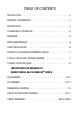
TABLE OF CONTENTS INTRODUCTION . . . . . . . . . . . . . . . . . . . . . . . . . . . . . . . . . . . . . . . . . . .4 WARRANTY INFORMATION . . . . . . . . . . . . . . . . . . . . . . . . . . . . . . . . . . .4 SPECIFICATION . . . . . . . . . . . . . . . . . . . . . . . . . . . . . . . . . . . . . . . . . . . .4 TECHNIQUES OF OPERATION . . . . . . . . . . . . . . . . . . . . . . . . . . . . . . . . .5 WARNINGS . . . . . . . . . . . . . . . . . . . . . . . . . . . . . . . . . . . . . . . . . . . . . . .
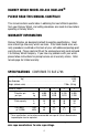
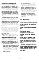
RAMSEY WINCH MODEL HD-234 RAM-LOK® PLEASE READ THIS MANUAL CAREFULLY. This manual contains useful ideas in obtaining the most efficient operation from your Ramsey Winch, and safety procedures one needs to know before operating a Ramsey Winch. WARRANTY INFORMATION Ramsey Winches are designed and built to exacting specifications. Great care and skill go into every winch we make. If the need should arise, warranty procedure is outlined on the back of your self-addressed postage paid warranty card.
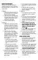
2. TO ENGAGE CLUTCH, lift up knob then release. See warning label located by shifter knob. Run the winch in reverse until the shifter knob snaps fully in or until the cable drum starts turning. At this point make sure the shifter knob is all the way in. The plastic plug in top of clutch housing may be removed, for inspection of clutch to assure total engagement. After the clutch is fully engaged, the winch is ready for winching in the cable.
4. Check alignment of chain and sprockets and adjust as required to minimize wear. 5. Inspect the cable. If the cable has become frayed with broken strands, replace immediately. WINCH MAINTENANCE Adhering to the following maintenance schedule will keep your winch in top condition and performing as it should with a minimum of repair. A. WEEKLY 1. Check the oil level and maintain it to the oil level plug. If oil is leaking out, determine location and repair. 2.
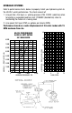
HYDRAULIC SYSTEMS Refer to performance charts, below, to properly match your hydraulic system to the HD-234 winch performance. The charts consist of: 1. Line pull (lbs.) first layer vs. working pressure (PSI). STATIC (solid line) refers to hoisting a suspended load from rest; DYNAMIC (dashed line) refers to maintaining the motion of a moving load. 2. Line speed, first layer (FPM) vs. gallons per minute (GPM). Performance based on a motor displacement of 3.6 cubic inches with 15 GPM maximum flow rate.
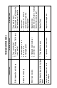
1. Drag brake disc worn. 1. Hydraulic motor shaft seal. Cable birdnests when clutch is disengaged Hydraulic fluid leaks out hole in motor adapter 1. Replace damaged seal. 1. Replace Discs. 1. Replace motor. 2. Check flow rate. Refer to Hydraulic Systems flow chart page 7. Oil leaks from housing 1. Hydraulic motor worn out. 2. Low flow rate. 1. Replace seal. 2. Drain excess oil. Refer to Techniques of Operation. 3. Replace gasket. 1. Seal damaged or worn. 2. Too much oil. 3. Damaged gasket.
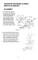
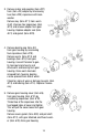
INSTRUCTIONS FOR OVERHAUL OF RAMSEY MODEL HD-234 RAM-LOK® DIS-ASSEMBLY 1. Drain oil from gear housing by removing (item #36) plug from bottom of gear housing. Remove plug (Item #35) from top of gear housing. Remove adapter rod (item #26) by driving pin (item #37) from shifter shaft of winch. Remove mounting frame (item #1) from winch by removing hardware shown. 2. Remove clutch housing (item #9) and clutch (item #5) from winch assembly. Remove two keys (item #31) from keyways.
3. Remove motor and coupling (item #27) from (item #3) adapter by unscrewing two (item #23) capscrews with lockwasher. Remove key (item #11) from worm shaft. Unscrew four capscrews (item #19) and remove adapter from gear housing. Replace adapter seal (item #41) and gasket (item #29). 4. Remove bearing cap (item #4) from gear housing by unscrewing four capscrews (item #18). Remove worm (item #13) and bearings (item #14) from gear housing.
6. Check for signs of wear on gear teeth. If replacement of gear is necessary, replace as follows: a) Press gear (item #8) from shaft (item #12). b) Examine shaft keys and keyways. If distortion of keys and/or keyways is evident, shaft and keys should be replaced. c) Use a soft hammer to gently tap keys (item #32) into keyways. Press gear (item #8) over shaft and keys. Gear must be centered over keys. 7. Remove seal (item #42) from back of (item #10) gear housing.
10.Check cover bushing (item #15) for signs of wear. If necessary remove old bushing and press bushing into place. RE-ASSEMBLY 11.Apply grease to end of shaft, opposite gear. Apply grease to bushing in gear housing (item #10). Place greased end of shaft through thrust washer (item #46) and bushing in gear housing (item #10). Place gasket (item #30) onto gear housing cover (item #6). Apply grease to gear end of shaft and cover bushing.
.Press bearing (item #14) onto worm and into housing. NOTE: Be sure that thick shoulder of bearings outer race (side with manufacturer's name and part number) is out, away from worm threads. Place gasket (item #29) onto adapter (item #3). Attach adapter to gear housing using four (4) capscrews (item #22). TIGHTEN CAPSCREWS TO 12 FT. LBS. (16.3 Nm.) EACH. Insert key (item #11) into keyway of worm shaft. Slide tapered end of coupling (item #27) over end of worm shaft.
15.Place thrust washer (item #46) over end of drum shaft and slide downward until spacer rests on drum. Press drum downward to compress springs in gear housing. Insert keys (item #31) into keyways with sharp edge of keys pointing outward and notched end of keys upward. A rubber or brass mallet will be needed to gently tap keys into position. Apply grease to keys and end of shaft. place jaw clutch (item #5) over end of shaft and slide jaw clutch over keys. Set clutch housing (item #9) over end of drum shaft.
.31 2.50 13.12 11.94 7.25 DIA. 19.56 3.50 DIA. 29.75 Model HD-234 Ram-Lok® FRAME ASSEMBLY #242174 5.13 7.78 2.50 .78 1.91 1.12 5.81 4.00 2.12 3.63 3.71 6.87 6.21 12.44 (REF.) 3.
1 1 1 1 1 1 1 1 1 1 1 1 1 2 4 4 1 14 2 6 4 2 1 1 2 3 4 5 6 7 8 9 10 11 12 13 14 15 16 17 18 20 21 22 23 24 414277 414282 414842 414952 416059 *SEE NOTE 276057 300057 316083 324160 328152 332105 334183 338312 338273 342027 357479 368203 402002 412003 412045 413013 414038 PART NO. SETSCREW 3/8-16NCX1/2 LG. SOC. HD CAPSCREW 3/8-16NC X 1 LG HX HD GR.5 CAPSCREW 3/8=16NCX1-1/4 LG. SOC. HD. GR.5 CAPSCREW 1/4-20NCX1-3/4LG. SOC. HD. L/W CAPSCREW 1/2-13NCX1-1/2 LG. SOC. HD.
Model HD-234 Ram-Lok®
NOTES
NOTES
LIMITED WARRANTY RAMSEY WINCH warrants each new RAMSEY winch to be free from defects in material and workmanship for a period of one (1) year from date of purchase. The obligation under this warranty, statutory or otherwise, is limited to the replacement or repair at the Manufacturer's factory, or at a point designated by the Manufacturer, of such part that shall appear to the Manufacturer, upon inspection of such part, to have been defective in material or workmanship.