
Use and Care Manual


21
Installation Instructions
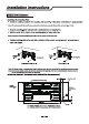
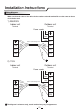
Make sure that the color of the wires in the outdoor unit and terminal No. are the same as those
of the indoor unit.
Wiring diagram
The diagram is reference only, actual terminal may vary in appearance.
Terminal
Indoor unit
1) 208/230V
Terminal
Outdoor unit
Power connecting cord
Green
White
Red
Black
1(N)
2(L)
3(SI)
Green
White
Red
Black
1(N)
2(L)
3(SI)
Power supply
L1
L2
GN
WHT
BLK
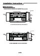
Terminal
Indoor unit
2) 115V
Terminal
Outdoor unit
Power connecting cord
Green
White
Red
Black
1(N)
2(L)
3(SI)
Green
White
Red
Black
1(N)
2(L)
3(SI)
Power supply
N
L
GN
WHT
BLK