MULTI·ZONE DUCTLESS INVERTER SPLIT AIR CONDITIONER WITH HEAT PUMP • INSTALLATION MANUAL • WALL MOUNTED TYPE INDOOR UNIT IMPORTANT NOTE: • Read this manual carefully before installing or operating your new air conditioning unit. Make sure to save this manual for future reference. This manual only describes features of the INDOOR UNIT in depth.
Table of Contents Installation Manual 0 Safety Precautions........................... 4 1 Accessories........................................6 2 Installation Summary - Indoor Unit........ 8 3 Unit Parts..........................................10 4 Indoor Unit Installation ......... 11 1. Select installation location ........................... 2. Attach mounting plate to wall .................. 3. Drill wall hole for connective piping ....... 4. Prepare refrigerant piping ........................... 5.
6 Refrigerant Piping Connection ........ 25 A. Note on Pipe Length ............................................................. B. Connection Instructions – Refrigerant Piping ............... 1. Cut pipe ............................................................................... 2. Remove burrs ..................................................................... 3. Flare pipe ends .................................................................. 4. Connect pipes ......................................
Safety Precautions Read safety precautions before installation Incorrect installation due to ignoring instructions can cause serious damage or injury. The seriousness of potential damage or injuries is classified as either a WARNING or CAUTION. This symbol indicates that ignoring instructions may cause death or serious injury. WARNING This symbol indicates that ignoring instructions may cause moderate injury to your person, or damage to your unit or other property.
WARNING 6. For all electrical work, follow all local and national wiring standards, regulations, and the installation manual. You must use an independent circuit and single outlet to supply power. Do not connect other appliances to the same outlet. Insufficient electrical capacity or defects in electrical work can cause electrical shock or fire. 7. For all electrical work, use the specified cables. Connect cables tightly and clamp them securely to prevent external forces from damaging the terminal.
1 Accessories The air conditioning system comes with the following accessories. Use all of the installation parts and accessories to install the air conditioner. Improper installation may result in water leakage, electrical shock, fire, or equipment failure. Name Shape Quantity Mounting plate 1 Clip anchor 5 Mounting plate fixing screw ST3.
Shape Name Quantity User's manual 1 Installation manual 1 Quick-Start Guide 1 Liquid side Conn ecting pipe assembly Ø 1/ 4 in (6.35 mm) Ø 3/ 8 in (9.52 mm) Ø 3/ 8 in (9.52 mm) Gas side Ø 1/ 2 in (12.7 mm) 25 Feet Included; for longer line sets, consult an HVAC professional - additional freon may be needed.
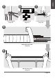
Installation Overview Installation Summary - Indoor Unit 1 2 5.9 in (15 cm) 4.75 in (12 cm) 2 4.75 in (12 cm) 90.55 in (2.
6 Installation Overview 5 7 1(L) 2(N) 3(S) Connect piping (Page 25) Connect wiring (Page 17) Prepare drain hose (Page 14) 8 Wrap piping and cable (Page 18) 9 STEP 8 Mount indoor unit (Page 18) Page 9
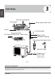
3 Unit Parts Installation Overview Wall mounting plate Front panel Power cable (some units) Louver Drainage pipe Functional Filter (On Front of Main Filter - Some Units) Signal cable Refrigerant piping Remote control (some units) ON/OFF TEMP MODE SWING SILENCE FP FAN SPEED SWING TIMER ON SLEEP TIMER OFF TURBO SELF CLEAN LED FOLLOW ME LOCK RESET Remote holder Outdoor unit power cable some units) Fig. 2.1 NOTE ON ILLUSTRATIONS Illustrations in this manual are for explanatory purposes.
4 Indoor Unit Installation Indoor Unit Installation Installation Instructions – Indoor Unit PRIOR TO INSTALLATION Before installing the indoor unit, refer to the label on the product box to make sure that the model number of the indoor unit matches the model number of the outdoor unit.
Refer to the following diagram to ensure proper distance from walls and ceiling: 5.9 in (15 cm) or more Indoor Unit Installation 4.75 in (12 cm) or more 4.75 in (12 cm) or more 90.55 in (2.3 m) or more Fig. 3.1 Step 2: Attach mounting plate to wall Step 3: Drill wall hole for connective piping The mounting plate is the device on which you will mount the indoor unit.
7.05 in (179 mm) Outdoor 4 in (101 mm) 1.95 in (49 mm) 5.35in(136mm) 1.45 in (37 mm) 13.7 in (348.4 mm) 11.4 in (290 mm) Indoor unit outline Left rear wall hole 2.5 in (65 mm) 1.95 in (49 mm) Indoor Wall 28.45 in (722 mm) Right rear wall hole 2.5 in (65 mm) 0.2-0.3 in (5 - 7 m m) Model A 1.7 in (43 mm) Indoor unit outline Left rear wall hole 2.5 in (65 mm) 1.7 in (43 mm) 11.7 in (297 mm) 5.05in(128mm) 1.7 in (43 mm) 9.15 in (232 mm) 7.55 in (192 mm) Right rear wall hole 2.
Step 4: Prepare refrigerant piping The refrigerant piping is inside an insulating sleeve attached to the back of the unit. You must prepare the piping before passing it through the hole in the wall. Refer to the Refrigerant Piping Connection section of this manual for detailed instructions on pipe flaring and flare torque requirements, technique, etc. Indoor Unit Installation 1. Based on the position of the wall hole relative to the mounting plate, choose the side from which the piping will exit the unit.
Step 5: Connect drain hose By default, the drain hose is attached to the lefthand side of the unit (when you’re facing the back of the unit). However, it can also be attached to the right-hand side. PLUG THE UNUSED DRAIN HOLE To prevent unwanted leaks, you must plug the unused drain hole with the rubber plug provided. 1. To ensure proper drainage, attach the drain hose on the same side that your refrigerant piping exits the unit. CORRECT 2.
BEFORE PERFORMING ELECTRICAL WORK, READ THESE REGULATIONS 1. All wiring must comply with local and national electrical codes and must be installed by a licensed electrician. 2. All electrical connections must be made according to the Electrical Connection Diagram located on the panels of the indoor and outdoor units. 3. If there is a serious safety issue with the power supply, stop work immediately.
Step 6: Connect signal cable The signal cable enables communication between the indoor and outdoor units. You must first choose the right cable size before preparing it for connection. Cable Types Indoor Power Cable (if applicable): H05VV-F or H05V2V2-F • Outdoor Power Cable: H07RN-F • Signal Cable: H07RN-F Minimum Cross-Sectional Area of Power and Signal Cables North America AWG Appliance Amps (A) The air conditioner’s circuit board (PCB) is designed with a fuse to provide overcurrent protection.
6. Feed the signal wire through this slot, from the back of the unit to the front. 7. Facing the front of the unit, match the wire colors with the labels on the terminal block, connect the u-lug, and firmly screw each wire to its corresponding terminal. CAUTION Indoor Unit Installation DO NOT MIX UP LIVE AND NULL WIRES This is dangerous and can cause the air conditioning unit to malfunction. 8.
If refrigerant piping is already embedded in the wall, do the following: 1. Hook the top of the indoor unit on the upper hook of the mounting plate. 2. Use a bracket or wedge to prop up the unit, giving you enough room to connect the refrigerant piping, signal cable, and drain hose. Refer to Fig. 3.13 for an example. 3. Connect drain hose and refrigerant piping (refer to Refrigerant Piping Connection section of this manual for instructions). 4.
5 Outdoor Unit Installation 24 in (60 cm) above Outdoor Unit Installation Installation Instructions – Outdoor Unit Step 1: Select installation location Before installing the outdoor unit, you must choose an appropriate location. The following are standards that will help you choose an appropriate location for the unit. Proper installation locations meet the following standards: Meet all spatial requirements shown in Installation Space Requirements ( Fig. 4.
SPECIAL CONSIDERATIONS FOR EXTREME WEATHER If the unit is exposed to heavy wind: Install the unit so that the air outlet fan is at a 90° angle to the direction of the wind. If needed, build a barrier in front of the unit to protect it from extremely heavy winds. See Fig. 4.2 and Fig. 4.3 below: Strong wind If the drain joint comes with a rubber seal (see Fig. 4.4 - A), do the following: 1. Fit the rubber seal on the end of the drain joint that will connect to the outdoor unit. 2.
Step 3: Anchor outdoor unit The outdoor unit can be anchored to the ground or to a wall-mounted bracket. W A UNIT MOUNTING DIMENSIONS B Air inlet D The following is a list of different outdoor unit sizes and the distance between their mounting feet. Prepare the installation base of the unit according to the dimensions below. Air inlet Fig. 4.5 A Air inlet Outdoor Unit Dimensions (in/mm) WxHxD W Air outlet Mounting Dimensions Distance A (in/mm) Distance B (in/mm) 18.10” (460) 27.5” x 21.
If you will install the unit on a wall-mounted bracket, do the following: CAUTION Before installing a wall-mounted unit, make sure that the wall is made of solid brick, concrete, or similarly strong material. The wall must be able to support at least four times the weight of the unit. 1. Mark the position of bracket holes based on dimensions in the Unit Mounting Dimensions chart. 2. Pre-drill the holes for the expansion bolts. 4. Place a washer and nut on the end of each expansion bolt. 5.
PAY ATTENTION TO LIVE WIRE WARNING BEFORE PERFORMING ANY ELECTRICAL OR WIRING WORK, TURN OFF THE MAIN POWER TO THE SYSTEM. 1. Prepare the cable for connection: USE THE RIGHT CABLE • Indoor Power Cable (if applicable): H05VV-F or H05V2V2-F • Outdoor Power Cable: H07RN-F • Signal Cable: H07RN-F WARNING ALL WIRING MUST BE PERFORMED STRICTLY IN ACCORDANCE WITH THE WIRING DIAGRAM LOCATED INSIDE THE OUTDOOR UNIT S’ WIRE COVER. 2. Unscrew the electrical wiring cover and remove it.
6 Refrigerant Piping Connection The length of refrigerant piping will affect the performance and energy efficiency of the unit. Nominal efficiency is tested on units with a pipe length of 16.5 ft (5 m). Refer to the table below for specifications on the maximum length and drop height of piping. Maximum Length and Drop Height of Refrigerant Piping per Unit Model Model R410A Inverter Split Air Conditioner Capacity (BTU/h) Max. Length (ft) Max.
DO NOT DEFORM PIPE WHILE CUTTING Flare nut Be extra careful not to damage, dent, or deform the pipe while cutting. This will drastically reduce the heating efficiency of the unit. Copper pipe Step 2: Remove burrs Burrs can affect the air-tight seal of the refrigerant piping connection. They must be completely removed. Fig. 5.3 1. Hold the pipe at a downward angle to prevent burrs from falling into the pipe. 4. Remove PVC tape from the ends of the pipe when ready to perform flaring work. 2.
6. Place the flaring tool onto the form. 7. Turn the handle of the flaring tool clockwise until the pipe is fully flared. 8. Remove the flaring tool and flare form, then inspect the end of the pipe for cracks and even flaring. Instructions for Connecting Piping to Indoor Unit 1. Align the center of the two pipes that you will connect. See Fig. 5.7 . Step 4: Connect pipes When connecting refrigerant pipes, be careful not to use excessive torque or to deform the piping in any way.
Instructions for Connecting Piping to Outdoor Unit 1. Unscrew the cover from the packed valve on the side of the outdoor unit. (See Fig. 5.9) USE SPANNER TO GRIP MAIN BODY OF VALVE Torque from tightening the flare nut can snap off other parts of the valve. Valve cover Fig. 5.9 2. Remove the protective caps from the ends of the valves. 3. Align flared pipe end with each valve and tighten the flare nut as tightly as possible by hand. 4. Using a spanner, grip the body of the valve.
7 Air Evacuation MC Preparations and Precautions Air and foreign matter in the refrigerant circuit can cause abnormal rises in pressure, which can damage the air conditioner, reduce its efficiency, and cause injury. Use a vacuum pump and manifold gauge to evacuate the refrigerant circuit, removing any non-condensable gas and moisture from the system.
3. Open the low pressure side of the manifold gauge. Keep the high pressure side closed. 4. Turn on the vacuum pump to evacuate the system. 5. Run the vacuum for at least 15 minutes, or until the compound meter reads -76 cm HG (-10 5 Pa). 6. Close the low pressure side of the manifold gauge and turn off the vacuum pump. 7. Wait 5 minutes, then check that there has been no change in system pressure. 8.
Electrical and Gas Leak Checks Electrical Safety Checks After installation, confirm that all electrical wiring is installed in accordance with local and national regulations, and according to the installation manual. BEFORE TEST RUN Check Grounding Work Measure grounding resistance by visual detection and with grounding resistance tester. Grounding resistance must be less than 4.
9 Test Run Before Test Run Only perform the test run after you have completed the following steps: • • • Electrical Safety Checks – Confirm that the unit’s electrical system is safe and operating properly Gas Leak Checks – Check all flare nut connections and confirm that the system is not leaking Confirm that gas and liquid (high and low pressure) valves are fully open Test Run Instructions You should perform the test run for at least 30 minutes. 1. Connect power to the unit.
DOUBLE CHECK PIPE CONNECTIONS During operation, the pressure of the refrigerant circuit will increase. This may reveal leaks that were not present during your initial leak check. Take time during the test run to double-check that all refrigerant pipe connection points do not have leaks. Refer to the Gas Leak Check section for instructions. 5. After the test run is successfully complete and you confirm that all checks points in the List of Checks to Perform have PASSED, do the following: a.
PRODUCT & INSTALLATION RECORD For your convenience, please record the model and serial numbers of your new equipment in the spaces provided. This information, along with the installation data and dealer contact information, will be helpful should your system require maintenance or service. UNIT INFORMATION Model No. Serial No.
MULTI·ZONE DUCTLESS INVERTER SPLIT AIR CONDITIONER WITH HEAT PUMP »OWNER'S MANUAL« WALL MOUNTED TYPE INDOOR UNIT IMPORTANT NOTE: • Read this manual carefully before installing or operating your new air conditioning unit. Make sure to save this manual for future reference. • This manual only describes features of the INDOOR UNIT in depth.
Precautions WARNING Operation and Maintenance This appliance can be used by children ages 8 years and above and persons with reduced physical, sensory, or mental capabilities or lack of experience and knowledge. Ensure that they have been given supervision or instruction concerning use of the appliance in a safe way and understand the hazards involved. Children should not play with the appliance. Cleaning and user maintenance should not be made by children without supervision.
WARNING To avoid personal injury or damage, only allow qualified professionals to perform maintenance. Please contact your dealer when you need to repair your air conditioner; do not repair it by yourself. This may cause electric shock or damage. Do not extend your fingers or objects into the air inlet or air outlet. This may cause personal injury or damage. Do not block the air inlet or air outlet. This may cause malfunction. Spilling water on the remote control may ruin it.
WARNING Attachment To avoid personal injury or damage, allow installation to be performed by qualified professionals. Qualified professionals should follow the electric safety regulations when installing the unit. In accordance with local safety regulations, use a qualified power supply circuit and circuit break. To avoid malfunction, install the circuit break. An all-pole disconnection switch with a contact separation of at least 1/8 in (3 mm) in all poles should be connected in fixed wiring.
WARNING Do not add power before finishing installation. If the supply cord is damaged, it must be replaced by the manufacturer, the service agent, or similarly qualified persons for a hazard to be avoided. Because the temperature of the refrigerant circuit will be high, ensure that the interconnection cable is kept away from the copper tube. The appliance should be installed in accordance with national wiring regulations.
WARNING For the air conditioner model with a plug, the plug should be reachable after installation is complete. For the air conditioner model without a plug, a circuit break must be installed in the line. Only a qualified professional should relocate the air conditioner. Personal injury or damage may result if you try to move it yourself. Select a location that is out of reach of children and far away from animals or plants. If this is impossible, please add a fence for safety purposes.
Unit Parts Power cable (some units ) Front panel Louver Remote control Functional filter (on front of main filter - some units) ON/OFF TEMP MODE SWING SILENCE FP FAN SPEED SWING TIMER ON SLEEP TIMER OFF TURBO SELF CLEAN LOCK LED FOLLOW ME RESET Remote holder (some units) Display window “ ” for 3 seconds when: • TIMER ON is set • FRESH, SWING, TURBO, or SILENCE features are turned on “ ” for 3 seconds when: • TIMER OFF is set • FRESH, SWING, TURBO, or SILENCE features are turned off “ ”
Achieving Optimal Performance Unit Specifications and Features Optimal performance for the COOL, HEAT, and DRY modes can be achieved in the following temperature ranges. When your air conditioner is used outside of these ranges, certain safety protection features will activate and cause the unit to perform less than optimally.
Other Features • Auto-Restart If the unit loses power, it will automatically restart with the prior settings once power has been restored. • Anti-mildew (some units) When turning off the unit from COOL, AUTO (COOL), or DRY modes, the air conditioner will continue to operate at very low power to dry up condensed water and prevent mildew growth. • Wi-Fi Control (some units) Wi-Fi control allows you to control your air conditioner using your mobile phone and a Wi-Fi connection.
Unit Specifications and Features • Setting Angle of Airflow Setting the Vertical Angle of Airflow While the unit is on, use the SWING/DIRECT button to set the direction (vertical angle) of airflow. 1. Press the SWING/DIRECT button once to activate the louver. Each time you press the button, it will adjust the louver by 6°. Press the button until the direction you prefer is reached. 2. To make the louver swing up and down continuously, press and hold the SWING/ DIRECT button for 3 seconds.
Unit Specifications and Features • Sleep Operation The SLEEP function is used to decrease energy use while you sleep (and don’t need the same temperature settings to stay comfortable). This function can only be activated via remote control. Press the SLEEP button when you are ready to go to sleep. When in COOL mode, the unit will increase the temperature by 2°F ( 1°C) after 1 hour, and will increase an additional 2°F (1°C) after another hour.
Manual Operation (Without Remote) How to Operate Your Unit without the Remote Control Manual Operation (Without Remote) In the event that your remote control fails to work, your unit can be operated manually with the MANUAL CONTROL button, located on the indoor unit. Note that manual operation is not a long-term solution, and that operating the unit with your remote control is strongly recommended. 2 CAUTION The manual button is intended for testing purposes and emergency operation only.
3 Care and Maintenance Cleaning Your Indoor Unit BEFORE CLEANING OR MAINTENANCE ALWAYS TURN OFF YOUR AIR CONDITIONER SYSTEM AND DISCONNECT ITS POWER SUPPLY BEFORE CLEANING OR MAINTENANCE. CAUTION 6. Rinse the filter with fresh water, then shake off excess water. 7. Dry it in a cool, dry place and refrain from exposing it to direct sunlight. 8. When dry, re-clip the air freshening filter to the larger filter, then slide it back into the indoor unit. 9. Close the front panel of the indoor unit.
CAUTION • Before changing the filter or cleaning, turn off the unit and disconnect its power supply. • When removing the filter, do not touch metal parts in the unit. The sharp metal edges can cut you. • Do not use water to clean the inside of the indoor unit. This can destroy the insulation and cause electrical shock. • Do not expose the filter to direct sunlight when drying. This can shrink the filter.
4 Troubleshooting SAFETY PRECAUTIONS If ANY of the following conditions occurs, turn off your unit immediately! • • • • • The power cord is damaged or abnormally warm You smell a burning odor The unit emits loud or abnormal sounds A power fuse blows or the circuit breaker frequently trips Water or other objects fall into or out of the unit DO NOT ATTEMPT TO FIX THESE YOURSELF! CONTACT AN AUTHORIZED SERVICE PROVIDER IMMEDIATELY! Common Issues The following problems are not a malfunction and in most situ
Issue Possible Causes A rushing air sound may occur when the louver resets its position. The indoor unit makes noises Due to expansion and contraction of the unit's plastic parts, a squeaking sound may occur after the unit is run in HEAT mode. Low hissing sound during operation: This is normal and is caused by refrigerant gas flowing through both the indoor and outdoor units.
Troubleshooting When troubles occur, please check the following points before contacting a repair company. Issue Possible Causes Solution The temperature setting may be higher than ambient Lower the temperature setting. room temperature. Poor cooling performance The heat exchanger on the indoor or outdoor unit is dirty. Clean the affected heat exchanger. The air filter is dirty. Remove the filter and clean it according to the instructions. The air inlet or outlet of either unit is blocked.
Issue The unit is not working The unit starts and stops frequently Poor heating performance Possible Causes Solution There is a power failure. Wait for the power to be restored. The power is turned off. Turn on the power. The fuse is burned out. Replace the fuse. The remote control batteries are Replace the batteries. dead. The unit’s 3-minute protection has been activated. Wait 3 minutes after restarting the unit. The timer is activated. Turn the timer off.
SYSTEM OPERATION COOLING OPERATION How it works: In cooling mode, your indoor unit will absorb heat from the room, then the outdoor unit will discharge the heat to the outdoors. The cooling capacity decreases as the outdoor temperature increases. This causes the air conditioner to work harder and longer to hold the selected room temperature. Indoor Coil Freeze Protection: Frost may form on the indoor coil during cooling operations when the outdoor temperature is below 50°F (10°C).
ENERGY-SAVING TIPS 1. Relaxing room temperature at night is OK: During the nighttime hours, you don’t require the same level of conscious cooling or heating. Try using Sleep Mode to gradually relax the room temperature and allow the unit to run less and save energy. 2. Curtains and shades: In the summer, you need to block the effects of the sun. Close window curtains and shades on the south and west sides of your home to help block solar heat. In winter, the sun is your friend.