MULTI·ZONE DUCTLESS INVERTER SPLIT AIR CONDITIONER WITH HEAT PUMP •INSTALLATION MANUAL• OUTDOOR CONDENSER IMPORTANT NOTE: • Read this manual carefully before installing or operating your new air conditioning unit. Make sure to save this manual for future reference. • This manual only describes features of the OUTDOOR UNIT in depth.
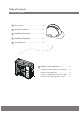
Table of Contents Installation Manual 1 Accessories .................................................................... 04 2 Safety Precautions ................................................. 05 3 Installation Overview .......................................... 06 4 Installation Diagram ............................................ 07 5 Specifications .............................................................. 08 Indoor Unit Installation ........................... 6 Outdoor Unit Installation .....
7 Refrigerant Piping Connection L .................. 12 N 8 Wiring ................................................................ 14 A. Outdoor Unit Wiring .......................... 14 B. Wiring Figure .......................................... 16 9 Air Evacuation ....................................................... 20 MC MC A. Evacuation Instructions ................................. 20 B. Note on Adding Refrigerant ...................... 21 10 Test Run ....................................
1 Accessories The air conditioning system comes with the following accessories. Use all of the installation parts and accessories to install the air conditioner. Improper installation may result in water leakage, electrical shock, or fire, or cause the equipment to fail. Name Installation plate Shape Quantity 1 Plastic expansion sheath 5-8 (depending on the models) Self-tapping screw AST3.
2 Safety Precautions Read safety precautions before installation Incorrect installation due to ignoring instructions can cause serious damage or injury. The seriousness of potential damage or injuries is classified as either a WARNING or CAUTION. WARNING Failure to observe a warning may result in death. The appliance must be installed in accordance with national regulations. Failure to observe a caution may result in injury or equipment damage.
Unit Installation Overview 3 Installation Overview INSTALLATION ORDER 1 Install the outdoor unit (Page 9) 2 3 4 MC Perform a test run (Page 22) Page 6 N Connect the wires (Page 14) Connect the refrigerant pipes (Page 12) 5 L MC Evacuate the refrigeration system (Page 20)
Installation Diagram More than 4.7 in More (12 с м) than 4.7 in More than 5.9 in (15 см) More (12 с м) than 4.7 (12 с in м) More than More th an 4.7 in (12 More than 23.6 in (60 см) 4.7 in (12 см) см) Mo r 3.9 e than in ( 10 см) 8.7 n7 ha et 00 2 n( i ) см han см) re t 0 Mo in (3 8 11. Mo 23 re th .6 in an (60 с м) r Mo Fig. 4.1 Safety Precautions CAUTION CAUTION This illustration is for explanation purposes only.
5 Specifications Power source voltage Number of connected units Stop time 1-5 units Voltage fluctuation within ± 10% of rated voltage Voltage drop during start within ± 15% of rated voltage Interval unbalance within ± 3% of rated voltage 3 minutes or more Table 5.2 1 drive 2 1 drive 3 Unit: ft/m 1 drive 4 1 drive 5 Max. length for all rooms 98.4/30 147.6/45 196.8/60 246/75 Max. length for one indoor unit 65.6/20 82/25 98.4/30 98.4/30 OU higher than IU 32.8/10 32.8/10 32.8/10 32.
6 Outdoor Unit Installation Outdoor Unit Installation Instructions Step 1: Select installation location √ √ √ √ √ The area must be free of combustible gases and chemicals. The pipe length between the outdoor and indoor units must not exceed the maximum allowable pipe length. If possible, DO NOT install the unit where it will be exposed to direct sunlight. If possible, make sure the unit is located far away from your neighbors’ property so that the noise from the unit will not disturb them.
Split Type Outdoor Unit (Refer to Fig 6.4, 6.5, 6.6, 6.10, and Table 6.1) Table 6.1: Length Specifications of Split Type Outdoor Unit (unit: inch/mm) Outdoor Unit Dimensions WxHxD H W Outdoor Unit Installation Fig. 6.4 W H Fig. 6.5 A D B Fig. 6.6 Page 10 Mounting Dimensions Distance A Distance B 760 x 590 x 285 (29.9 x 23.2 x 11.2) 20.85 (530) 11.4 (290) 810 x 558 x 310 (31.9 x 22 x 12.2) 21.6 (549) 12.8 (325) 845 x 700 x 320 (33.27 x 27.5 x 12.6) 22 (560) 13.
23.6”/60 cm above NOTE: The minimum distance between the outdoor unit and walls described in the installation guide does not apply to airtight rooms. Be sure to keep the unit unobstructed in at least two of the three directions (M, N, and P) (see Fig. 6.7). 11.8 ”/30 cm o ck m 0 ”/3 cm fro ba ll wa NOTE: When drilling the wall hole, make sure to avoid wires, plumbing, and other sensitive components. .8 11 n lef M t 23.6” /60 c 78 in m on right fr N 3.
7 Refrigerant Piping Connection Safety Precautions WARNING Refrigerant Piping Connection • All field piping must be completed by a licensed technician and must comply with local and national regulations. • When the air conditioner is installed in a small room, measures must be taken to prevent the refrigerant concentration in the room from exceeding the safety limit in the event of refrigerant leakage.
4. Remove the PVC tape from the ends of the NOTE: Use both a spanner and a torque wrench pipe when you're ready to perform the flaring when connecting or disconnecting pipes to/from work. the unit. 5. Clamp the flare form on the end of the pipe. The end of the pipe must extend beyond the flare form. Flare form Pipe Fig. 7.4 6. Place the flaring tool onto the form. 7. Turn the handle of the flaring tool clockwise until the pipe is fully flared.
8 Wiring Safety Precautions WARNING • • • • • • Wiring • • Be sure to disconnect the power supply before working on the unit. All electrical wiring must be done according to local and national regulations. Electrical wiring must be done by a qualified technician. Improper connections may cause electrical malfunction, injury, and fire. An independent circuit and single outlet must be used for this unit. DO NOT plug another appliance or charger into the same outlet.
Table 8.2: Other Regions Rated Current of Appliance (A) Nominal Cross-Sectional Area (mm²) 5. Insulate unused wires with electrical tape. Keep them away from any electrical or metal parts. ≤6 0.75 6. Reinstall the cover of the electric control box. 6 - 10 1 10 - 16 1.5 16 - 25 2.5 25 - 32 4 32 - 45 6 B. Using wire strippers, strip the rubber jacket from both ends of the signal cable to reveal about 5.9 in (15 cm) of the wires inside. C. Strip the insulation from the ends of the wires. D.
Wiring Figure CAUTION Connect the connective cables to the terminals as identified with their respective matched numbers on the terminal block of the indoor and outdoor units. For example, see the following US models: Terminal L1(A) on the outdoor unit must connect with terminal L1 on the indoor unit. NOTE: If the client wants to perform the wiring himself, refer to the following figures. Run the main power cord through the lower line-outlet of the cord clamp.
NOTE: If the client wants to perform the wiring himself, refer to the following figures.
Model E Model F Model G One-five models: Wiring Model A Model C Page 18 Model B Model D
Model E Model F Model G CAUTION Page 19 Wiring After the confirmation of the above conditions, prepare the wiring as follows: • Never fail to delegate an individual power circuit specifically for the air conditioner. For the method of wiring, use the circuit diagram posted on the inside of the control cover as a guide.
9 Air Evacuation Safety Precautions CAUTION • Use a vacuum pump with a gauge reading lower than -0.1 MPa and an air discharge capacity above 40 L/min. • The outdoor unit does not need vacuuming. DO NOT open the outdoor unit’s gas and liquid stop valves. • Ensure that the compound meter reads -0.1 MPa or below after 2 hours. If after 3 hours of operation the gauge reading is still above -0.1 MPa, check if there is a gas leak or water inside the pipe.
Note on Adding Refrigerant CAUTION • Refrigerant charging must be performed after wiring, vacuuming, and the leak test. DO NOT exceed the maximum allowable quantity of refrigerant or overcharge the system. Doing so may damage or impact the unit’s function. • Charging with unsuitable substances may cause explosions or accidents. Ensure that the appropriate refrigerant is used. • Refrigerant containers must be opened slowly. Always use protective gear when charging the system. • DO NOT mix refrigerant types.
Test Run Before Test Run A test run must be performed after the entire system has been completely installed. Confirm the following points before performing the test: a) The indoor and outdoor units are properly installed. b) Piping and wiring are properly connected. c) No obstacles are near the inlet and outlet of the unit that might cause poor performance or product malfunction. d) The refrigeration system does not leak. e) The drainage system is unimpeded and draining to a safe location.
Function of Automatic Wiring/Piping Correction 11 Automatic Wiring/Piping Correction Function The new product is able to automatically correct a wiring/piping error. Press the "check switch" on the outdoor unit PCB board for 5 seconds until the LED display shows "CE." This means the function is working. Approximately 5-10 minutes after the switch is pressed, "CE" will disappear, the wiring/piping error will be corrected, and the wiring/piping will be properly connected.
MULTI·ZONE DUCTLESS INVERTER SPLIT AIR CONDITIONER WITH HEAT PUMP »OWNER'S MANUAL« OUTDOOR CONDENSER IMPORTANT NOTE: • Read this manual carefully before installing or operating your new air conditioning unit. Make sure to save this manual for future reference. • This manual only describes features of the OUTDOOR UNIT in depth.
Table of Contents Owner’s Manual 1 Safety Precautions .................................................... 04 SAFETY FIRST 2 Unit Parts and Major Functions ......................... 3 Manual Operation and Maintenance ..............
4 Troubleshooting ................................. 10 a. Common Problems ................................. b. Troubleshooting Tips ...............................
Safety General Introduction Precautions 1 Safety Precautions Thank you for purchasing this air conditioner. This manual will provide you with information on how to operate, maintain, and troubleshoot your air conditioner. Following the instructions will ensure the proper function and extended lifespan of your unit. Please pay attention to the following signs: WARNING Failure to observe a warning may result in death. The appliance must be . installed in accordance with national regulations.
Unit Parts Wall-mounted type Fig. 2.1 Indoor unit 1. Panel frame 2. Rear air intake grille 3. Front panel 4. Air Purifying filter & Air filter(behind) 5. Horizontal louver 6. LCD display window 7. Vertical louver 8. Manual control button(behind) 9. Remote controller holder Outdoor unit 10. Drain hose, refrigerant connecting pipe 11. Connective cable 12. Stop valve 13. Fan hood Duct / Ceiling type Fig. 2.2 Indoor unit 1. Air outlet 2. Air inlet 3. Air filter 4. Electric control cabinet 5.
Floor and standing type(console) Compact four-way cassette type Unit Parts And Major Functions Fig. 2.4 Indoor unit 1. Air flow louver (at air outlet) 2. Air inlet(containing air filter) 3. Remote controller 4. Installation part 5. Display panel Indoor unit 1. Drain pump(drain water from indoor unit) 2. Drain hose 3. Air outlet 4. Air inlet 5. Air-in grill 6. Display panel 7. Remote controller Outdoor unit 6. Drain hose, refrigerant connecting pipe 7. Connective cable 8. Stop valve 9.
NOTE: For multi-split type air conditioners, one outdoor unit can be matched to different types of indoor units. All of the pictures in this manual are for demonstration purposes only. Your air conditioner may be slightly different, if similar in shape. The following pages introduce several kinds of indoor units that can be matched with the outdoor units. Unit Parts And Major Functions Operating Conditions Use the system under the following temperatures for safe and effective operation.
The air conditioner turns to FAN ONLY mode from COOL or HEAT (for cooling and heating models only) mode. Unit Parts And Major Functions When the indoor temperature reaches the set temperature setting, the compressor will stop automatically, and the air conditioner turns to FAN only mode. The compressor will start again when the indoor temperature rises on COOL mode or falls on HEAT mode to the set point.
Manual Operations And Maintenance Operation mode selection Maintenance If you plan to leave the unit idle for a long time, perform the following tasks: 1. Clean the indoor unit and air filter. 2. Select FAN ONLY mode and let the indoor fan run for a time to dry the inside of the unit. 3. Disconnect the power supply and remove the battery from the remote control. 4. Check the components of the outdoor unit periodically. Contact a local dealer or a customer service centre if the unit requires servicing.
4 Troubleshooting CAUTIONS If one of the following conditions occurs, switch off the power supply immediately and contact your dealer for further assistance. Troubleshooting • • • • • The operation light continues to flash rapidly after the unit has been restarted. The remote control buttons do not work. The unit continually trips fuses or circuit breakers. A foreign object or water enters the air conditioner. Other abnormal situations.
Problem Possible Causes Dust is emitted from either the indoor or outdoor unit The unit emits a bad odor The fan of the outdoor unit does not operate The unit may accumulate dust during extended periods of non-use, which will be emitted when the unit is turned on. This can be mitigated by covering the unit during long periods of inactivity. The unit may absorb odors from the environment (such as furniture, cooking, cigarettes, etc.) which will be emitted during operations.
SYSTEMOPERATION COOLING OPERATION How it works: In cooling mode, your indoor evaporator will absorb heat from the room, then the outdoor condenser will discharge the heat to the outdoors. The sophia cooling capacity decreases as the outdoor temperature increases. This causes the ali ce to work harder and longer to hold the selected room temperature. Indoor Coil Freeze Protection: Frost may form on the indoor coil during cooling operations when the outdoor temperature below 50°F (10°C).
ENERGY SAVING TIPS 1. Relaxing room temperatureat night is OK: During the nighttime hours you don’t require the same level of conscious cooling or heating. Try using Sleep Mode to gradually relax room temperature and allow the unit to run less and save energy. 2. Curtains and shades: In the summer, you need to block the effects of the sun. Close window curtains and shades on the south and west side of your home to help block solar heat. In winter, the sun is your friend.