
Installation Guide

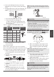
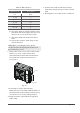
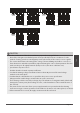
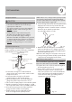
Table Of Contents

Table 8.2: Other Regions
Rated Current of
Appliance (A)
Nominal Cross-Sectional
Area (mm²)
≤ 6 0.75
6 - 10 1
10 - 16 1.5
16 - 25 2.5
25 - 32 4
32 - 45 6
Page 15
B. Using wire strippers, strip the rubber jacket
from both ends of the signal cable to reveal
about 5.9 in (15 cm) of the wires inside.
C. Strip the insulation from the ends of the
wires.
D. Using a wire crimper, crimp u-lugs on the
ends of the wires.
NOTE: While connecting the wires, please
strictly follow the wiring diagram (found inside
the electrical box cover).
2. Remove the electric cover of the outdoor unit.
If there is no cover on the outdoor unit,
disassemble the bolts from the maintenance
board and remove the protection board
(see Fig. 8.1).
Cover
Screw
Fig. 8.1
3. Connect the u-lugs to the terminals.
Match the wire colors/labels with the labels on
the terminal block, then rmly screw the u-lug
of each wire to its corresponding terminal.
4. Clamp down the cable with the designated
cable clamp.
5. Insulate unused wires with electrical tape.
Keep them away from any electrical or metal
parts.
6. Reinstall the cover of the electric control box.
Wiring