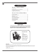
Operator’s Manual BVE SERIES Electric Motor / Diesel fired READ THIS MANUAL This manual contains important information for the use and safe operation of your RAMTEQ machine. FAILURE TO READ THIS MANUAL AND FOLLOW ITS INSTRUCTIONS PRIOR TO OPERATING OR ATTEMPTING ANY SERVICE OR MAINTENANCE PROCEDURE COULD RESULT IN SERIOUS INJURY OR DEATH TO YOU OR OTHER PERSONS; ALSO DAMAGE TO THE MACHINE OR TO OTHER PROPERTY. ® RAMTEQ ® 14275 northwest freeway Houston, TX 77040 phone: 713.983.6000 fax: 713.
Operator’s Manual Page Table of Contents Section 1 Operator’s Manual Unpacking....................................................................2 Safety Instructions and Warnings.............................3 Operating Instructions...............................................4 Maintenance Instructions...........................................5 Section 2 Parts and Service Manual Parts Diagram.............................................................7 Hose, Wand, & Gun...........
Operator’s Manual Page Safety Guidelines � WARNING READ THIS FIRST! Failure to read and observe all WARNING statements could result in severe bodily injury or death, possible injury to other persons, damage to machine or other property. DO NOT operate this machine in areas where open flames are not permitted. DO NOT store or use combustible materials on or near this machine. Use this equipment only in well ventilated areas.
Operator’s Manual Page Operating Instructions LOCATION GUIDELINES Locate the machine on a solid and level surface so that engine and pump crankcase oil lubricate components properly. Avoid areas where water can build up in the working area. Possible injury can occur caused by the surface becoming slippery from water build up. Locate the machine in a well-ventilated area and away from flammable materials or fumes. Be sure ventilation warnings are observed.
Operator’s Manual Page Maintenance Instructions MAINTENANCE PRECAUTIONS Do not permit acidic, caustic or abrasive fluids to be pumped through system. Periodically clean detergent inlet screen. This will ensure proper flow of water to the pump. High mineral content in water may adversely affect your machine and may require the use of a water softener to ensure proper operation. NEVER run the pump dry under any circumtances. Doing so will cause exteme damage to the pump.
Operator’s Manual Page Maintenance Instructions ELECTRODE SETTINGS Inspection of all wires, spring contacts and electrodes should be done periodically. � WARNING IF BLACK OR WHITE SMOKE VENTS FROM EXHAUST PORT UPON STARTING EQUIPMENT, DISCONTINUE USE AND ADJUST AIR BANDS BEFORE RESTARTING. OIL BURNER AIR BAND ADJUSTMENT RAMTEQ sets oil burners at sea level. Air bands may need adjustment at higher elevations to offer enhanced performance of the burner and extended life of the machine.
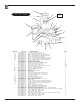
Operator’s Manual Page 13 BVE Parts Diagram 16 Exploded view on page 9. 14 12 17 15 11 18 19 3 20 10 2 9 8 1 6 7 5 Ref.
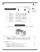
Operator’s Manual Page 4 5 Hose, Wand & Gun 2 1 3 Ref.# 1a 1b 1c 1d 1e 1f 1g 1h 1i 1j 1k 1m 2 3 4 5 Part # Description 270-00028-01 270-00028-02 270-00028-03 270-00028-04 270-00025-01 270-00025-02 270-00025-03 270-00025-04 270-00028-01 270-00028-02 270-00028-03 270-00028-04 265-00001-01 275-00001-01 552-00004-03 284-00001-01 Qty. Nozzle, Water #5.5 0º (BVE 500,600) Nozzle, Water #5.5 15º(BVE 500,600) Nozzle, Water #5.5 25º(BVE 500,600) Nozzle, Water #5.5 40º(BVE 500,600) Nozzle, Water #4.
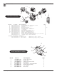
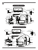
Operator’s Manual Page 3 4 5 9 2 8 BVE Burner Assembly 7 1a 6 1 Ref.# 1 2 3 4 5 5a 6 7 8 8a 9 Part # Description 251-00001-01 256-00001-02 245-00012-16 258-00002-02 252-00001-03 252-00001-02 253-00001-02 253-00002-02 254-00001-03 254-00001-02 577-00003-01 578-00001-01 280-00003-01 556-00001-01 Qty Fuel Pump w/ Solenoid 115v Main Burner Gasket Nozzle Electrode Pair Transformer 115v Transformer 208/230v Coupling Fan Wheel 6.25”x4.
Operator’s Manual Page 10 BVE 500, 600 Base Plumbing QETMAR GARDEN HOSE CONNECTOR 3/4 SWIVEL X 3/8 NPTM BULKHEAD FITTING 1/2 NPTF I.D. FLOAT TANK (REAR VIEW) FLOAT VALVE (2 PL.) LOW PRESSURE HOSE 1/2 I.D. X 50" CLAMP BAND Ø1/4 -5/8 (7 PL.) COUPLER, FRAME MOUNTED 3/8 NPTF X 3/8 NPTF ELBOW, BRASS 1/2 NPT X 1/2 BARB QUICK CONNECT COUPLER 3/8 NPTM X 3/8 MALE CLAMP BAND Ø0.4 - 0.9 TEE, POLYPROPYLENE 3/8 BARB X 3/8 BARB X 3/8 BARB ELBOW, BRASS 3/8 NPTM X 3/8 BARB NIPPLE, GALVANIZED STEEL 1/2 NPT X 2.
Operator’s Manual Page 11 BVE 750, 1000 base Plumbing QETMAR GARDEN HOSE CONNECTOR 3/4 SWIVEL X 3/8 NPTM BULKHEAD FITTING 1/2 NPTF I.D. NIPPLE, GALVANIZED STEEL 1/2 NPT X 2.5" LOW PRESSURE HOSE 1/2 I.D. X 50" CLAMP BAND Ø1/4 -5/8 (7 PL.) COUPLER, FRAME MOUNTED 3/8 NPTF X 3/8 NPTF (713) 983-6000 FLOAT TANK (REAR VIEW) FLOAT VALVE (2 PL.) RELIEF VALVE JE ADAMS 7468 (3500 PSI) ELBOW, BRASS 1/2 NPT X 1/2 BARB QUICK CONNECT COUPLER 3/8 NPTM X 3/8 MALE CLAMP BAND Ø0.4 - 0.
Operator’s Manual Page 12 BVE wiring Diagrams Wht BURNER MODULE Blk Burner Mtr Transformer for Ignitor Wht Fuel Solenoid Wht Blk Red 208-230V Blk BURNER SW Orange 208-230V Wht FLOW SW P1 1 BLK Orange 115V Blue PUMP SW Blue GRN Red Red GRN GRN WHT RED ELECTRICAL SCHEMATIC ORANGE BVE, XVE BASE BLK BLK WHT BLUE L2 L1 230 VOLT 1Ph UNITS BLK WHT F2 WHT F1 L2 RED H4 H2 H3 H1 T1 X1 L3 L1 M1 X2 RED Wiring Effective: 10/13/2004 95 96 ORANGE OL OL A2 OL M1 A1 BLUE
Operator’s Manual Page 13 BVE wiring Diagrams Wht BURNER MODULE Blk Burner Motor Transformer for Ignitor Wht CONTROL BOX Fuel Solenoid Wht Blk BURNER SW Blk Red Wht 208-230V Orange 208-230V FLOW SW P1 1 BLK Orange 115V Wht 5 Blue PUMP SW Blue HOURMETER 4 TIMER 1 2 3 GRN UNLOADER SW Red Red GRN GRN RED ELECTRICAL SCHEMATIC BVE, XVE UPGRADE BLK WHT L2 L1 230 VOLT 1Ph UNITS BLK WHT F2 WHT F1 L2 RED H4 H2 H3 H1 T1 X1 L3 L1 RED Wiring Effective: 9/27/2005 95 M1
Operator’s Manual Page 14 BVE wiring Diagrams Wht Blk Burner Mtr BURNER MODULE Transformer for Ignitor Wht CONTROL BOX Fuel Solenoid Wht Blk Q P1 FLOW SW 4 1 P 3 BLK Orange 3 Red 208-230V Blk BURNER SW 115V Orange 208-230V Wht Blue PUMP SW Blue Red Red WHT ELECTRICAL SCHEMATIC RED BVE, XVE BASE ORANGE BLK BLK BLUE WHT L2 230 VOLT 3Ph UNITS L1 BLK F2 T1 X1 WHT L2 WHT F1 H4 H2 H3 H1 BLK L3 L1 M1 X2 RED Wiring Effective: 10/13/2004 RED 95 96 ORANGE OL OL
Operator’s Manual Page 15 BVE wiring Diagrams Wht BURNER MODULE Blk Burner Mtr Transformer for Ignitor Wht Fuel Solenoid CONTROL BOX Wht Blk Red 208-230V Blk BURNER SW Orange 208-230V Wht FLOW SW P1 1 BLK Orange 115V Wht 5 Blue PUMP SW Blue HOURMETER 4 TIMER 1 2 3 GRN UNLOADER SW Red Red GRN GRN WHT RED ELECTRICAL SCHEMATIC ORANGE BLK BLK BVE, XVE UPGRADE WHT BLUE L2 L1 BLK WHT F2 WHT L2 F1 230 VOLT 3Ph UNITS RED H4 H2 H3 H1 T1 X1 L3 L1 M1 X2 Motor Contact
Operator’s Manual Page 16 bve wiring Diagrams Wht BURNER MODULE Blk Burner Mtr BURNER MODULE Transformer for Ignitor ORG Wht Fuel Solenoid CONTROL PANEL RED Wht BURNER SW Blk Wht FLOW SW P 1 Wht Blk THERMOSTAT SW1 Wht 115V Blk PUMP SW GRN Red GRN RED WHT GRN RED GRN ELECTRICAL SCHEMATIC BLK L1 BLK WHT BLK WHT F2 WHT L2 F1 H4 H2 H3 H1 460 VOLT 3Ph UNITS RED RED BLK T1 X1 BVE, XVE BASE L2 L3 L1 M1 X2 Motor Contactor w/ thermal overload protection RED 95 96 OL
Operator’s Manual Page 17 BVE wiring Diagrams Wht BURNER MODULE Blk Burner Mtr BURNER MODULE Transformer for Ignitor ORG Wht Fuel Solenoid CONTROL PANEL RED Wht BURNER SW Blk Wht BLUE FLOW SW BLUE P 1 THERMOSTAT SW1 Wht 115V Blk 5 PUMP SW HOURMETER 4 TIMER 1 2 K 3 GRN UNLOADER SW Red GRN RED WHT GRN ELECTRICAL SCHEMATIC RED BVE, XVE UPGRADE GRN BLK L1 BLK 460 VOLT 3Ph UNITS L2 WHT BLK WHT WHT F2 L2 F1 H4 H2 H3 H1 T1 X1 RED BLK L3 L1 AUX 14 Wiring Effe
Operator’s Manual Page 18 troubleshooting problem Low Water Pressure cause action Insufficient water source Old or incorrect nozzle Plumbing or hose leak Obstruction in spray nozzle Chemical valve open Unloader valve worn Pump valves dirty or worn Check hose size/water source Replace nozzle Tighten, repair or replace leak Clean or replace nozzle Close valve or submerge hose Replace unloader Clean or replace packing/valves No Chemical Flow Detergent valve closed Low detergent lev
RAMTEQ Limited One Year WARRANTY Ramteq Incorporated ("RAMTEQ") warrants that the Product you have purchased from RAMTEQ or from an Authorized RAMTEQ Reseller is free from defects in materials or workmanship under normal use for a period of one (1) year from the date of purchase. This warranty extends only to you, the original Purchaser. It is not transferable to anyone who subsequently purchases the Products from you.
Ramteq Manufacturers Warranty Period Click on pictures to open manufacturers website. 5 years 5 years 3 years 3 years 3 years 3 years 18 months 18/36 months Ramteq Pressure Washers 14275 NORTHWEST FREEWAY HOUSTON, TX 77040 1 year PHONE: 713.983.6000 FAX: 713.983.