88583 Rev D Suspension System RS6583B Chevrolet Silverado/GMC Sierra 88583 Rev D
READ ALL INSTRUCTIONS THOROUGHLY FROM START TO FINISH BEFORE BEGINNING INSTALLATION IMPORTANT NOTES! WARNING: This suspension system will enhance the offroad performance of your vehicle. It will handle differently, both on and off-road, from a factory equipped passenger car or truck. Extreme care must be used to prevent loss of control or vehicle rollover during abrupt maneuvers. Failure to drive this vehicle safely may result in serious injury or death to the driver and passengers.
N. The required installation time for this system is approximately 8 hours. Check off the box ( ) at the beginning of each step when you finish it. Then when you stop during the installation, it will be easier to find where you need to continue from. P. Rear axle offset may be noticed on some vehicles. The offset will vary somewhat with vehicle loading. Another factor is how centered the axle was under the body from the factory.
RS6583B Suspension System 4
PARTS LIST P/N 176132B 176385B 331 176138 176235 602617 7495 8051 8102 860176 860185 860410 860474 176137 420042 520041 860546 860547 DESCRIPTION Box 1 of 4 Aft Brace Subframe Box 2 of 4 Add-A-Leaf Aft Brace Bracket Axle Spacer Tie Rod End 9/16-18 x 2.57 x 11.0 U-bolt Riser Block Pin Kit .625 x .875 Pin U-bolt Hardware Kit 9/16-18 Nyloc Nut 9/16 SAE Washer Axle Spacer Hardware Kit M10-1.50x60 HHCS SAE Washer Spring Installation Kit 3/8-24 x 7.5 HHCS 3/8-24 Hi-Nut Center bolt Hardware Kit 3/8-24 x 5.
FRONT SUSPENSION VEHICLE PREPARATION & SWAY BAR REMOVAL NOTE: For vehicles equipped with Electronic Suspension Control (Autoride), separate brake hose from sensor link bracket. 1) Park the vehicle on a level surface. Set the parking brake and chock rear wheels. Measure and record the distance from the center of each wheel to the top of the fender opening. See illustration #1. 2) Remove the brake caliper anchor bolts. Remove the brake caliper and its mounting bracket as an assembly.
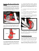
1) Attach right drop bracket 176386 to the passenger side differential frame mount with the original hardware. See illustration 5. Tighten nuts and bolts to 65 ft. lbs. 11) Remove the lower control arm pivot bolts. Remove the lower control arm. 12) Repeat steps 1 through 11 for the other side. FRONT DIFFERENTIAL REMOVAL (4WD ONLY) 1) Remove the four bolts that attach the crossmember to the lower control arm rear pockets. Remove the crossmember.
5) hose. COIL SPRING & SHOCK ABSORBER INSTALLATION Reattach the electrical connector and vent NOTE: New shock absorbers are not included with this kit and must be purchased separately. See Important Notes A and C. 6) Align reference marks and reattach the front drive shaft U-joint to the differential yoke. Tighten bolts to 22 ft. lbs. 1) Using a quality spring compressor, compress the coil spring until the tension is released from the shock absorber.
HALF SHAFT INSTALLATION (4WD Only) & STEERING KNUCKLE 4) Insert the half shaft into the hub. Attach left steering knuckle 176475 to the lower and upper ball joints with the original hardware. See illustration 12. Tighten the nut on the lower ball joint stud to 74 ft. lbs., and the nut on the upper ball joint stud to 37 ft. lbs. 1) Place axle spacer 176235 against the driver side differential flange. Align flange marks and place the half shaft flange against the spacer.
6) Attach the brake hose and ABS wire to the upper control arm with the original bolt and loop strap from kit 860547. Refer to illustration 14. Reconnect ABS wire. NOTE: For vehicles with Electronic Suspension Control, attach brake hose 170106 to top of sensor link bracket. See illustration 15. 176579 Illus. 13 3) Loosely attach the sway bar to the lower control arms with the original end link assemblies. BRAKE HOSE INSTALLATION 1) Install the brake rotor.
Illus. 16 5) For 2WD vehicles, temporarily attach aft brace bracket 176138 to the aft brace as shown in illustration 16. Using the slotted hole in the bracket as a template mark the mounting hole location on the transmission crossmember. Drill a 1/2” hole at the marked location. Remove bracket. Repeat for other side. 10) If applicable, cut the corner of the skid plate to avoid contact with the aft brace bracket. Reinstall the transfer case skid plate. 11) Install front wheels and lower vehicle to ground.
7) Carefully remove the C-clamps and set the helper spring aside. REAR SUSPENSION ADD-A-LEAF & RISER BLOCK INSTALLATION 8) Apply a small amount of grease to the top ends of Rancho Add-A-Leaf RS331. 1) Chock front wheels. Raise the rear of the vehicle and support the frame with jack stands. Remove the rear wheels. 2) Support the rear axle assembly with a floor jack. Remove both rear shock absorbers. Do not reuse OEM shock absorbers.
14) Insert a block pin from kit 8051 into the hole in the axle pad. Place the new riser block (15080) on the axle pad with the taller end of the block in the rear and the top hole offset to the front. See illustration 21. Illus. 22 BUMP STOP SPACER INSTALLATION 1) Remove the bolt holding the bump stop to the frame bracket. Remove the bump stop. Illus. 21 NOTE: Ignore the “up” stamped on the riser block for this application. All block imprinting faces downward.
FINAL CHECKS & ADJUSTMENTS BRAKE LINE BRACKET INSTALLATION 1) Attach the new brake line bracket 170014 to the rear differential with the 8mm hardware from kit 860569. See illustration 24. 1) Turn the front wheels completely left then right. Verify adequate tire, wheel, and brake hose clearance. Inspect steering and suspension for tightness and proper operation. 2) Carefully reshape the brake line and attach the junction block to the top of bracket 170014. Use the 5/16” hardware from kit 860569.