
Owners manual


10
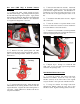
Illus. 13
3) Loosely attach the sway bar to the lower
control arms with the original end link assemblies.
BRAKE HOSE INSTALLATION
1) Install the brake rotor. Apply thread lock and
attach the caliper to the knuckle with the original
mounting bolts. Tighten the caliper mounting bolts to
129 ft. lbs.
2) Disconnect the brake tube from the hose at the
frame rail. Plug tube to prevent brake fluid seepage.
3) Remove the retainer clip and disconnect the
brake hose from the caliper. Discard copper washers.
If necessary, cut-off washer from bolt.
4) Attach new brake hose 170106 to the caliper
with the original bolt and new washers. Tighten bolt
to 38 ft. lbs. See illustration 14.
Illus. 14
5) Attach hose to tube at frame bracket. Install
retainer clip. Tighten fitting to 18 ft. lbs.
6) Attach the brake hose and ABS wire to the
upper control arm with the original bolt and loop strap
from kit 860547. Refer to illustration 14. Reconnect
ABS wire.
NOTE: For vehicles with Electronic Suspension
Control, attach brake hose 170106 to top of sensor link
bracket. See illustration 15.
Illus 15
7) Repeat steps 1 through 6 for the other side.
8) Bleed front brakes.
A
FT BRACE INSTALLATION
1) Using a silicon spray, lubricate two bushings
(520041) and one sleeve (420042) from kit 860474.
Press the bushings and sleeve into aft brace 176132B
as shown in illustration 16.
2) Repeat step 1 to install the rest of the bushings
and sleeves.
3) Loosely attach the aft braces to subframe
176385B with the hardware from kit 860474. See
illustration 16.
NOTE: Both aft braces should angle slightly outward
from front to rear.
4) If applicable, remove the transfer case skid
plate.
176579